LoPresti Cowl and Cooling Seminar
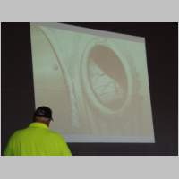
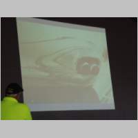
This info was provided by John Cox with the following note:"A key point is the LoPresti Poor Boy Tufting process to read cowl pressure corrections without the time and expense of Tufting. They take a quart of Turbine oil and mix it with a quart of engine oil and add black toner cartridge carbon to make a spray able solution. It looks like shit but can be sprayed with a cheap garden sprayer and washed off with degreaser. It allows the project coordinator to read the lines of backflow, high and low pressure more easily."
Now, on to the info...
|
|
What Makes an Inlet Good?
Yes, we really will
tell you….
- The total pressure behind a propeller blade does not change much with useful radius.
- In regions close to the spinner propeller blade sections can have bad profile due to stiffness requirements.
- Flow inches away from the spinner are low in energy and can even have reverse flow.
- Inlets that have their inside edge in contact with spinner contour so the inlet will always ingest this chopped up flow. This chopped up flow contributes to bad inlet performance.
- LoPresti inlets are set off from the spinner sufficiently so they only see high energy airflow.
Inlet Diffusers
Control and direct
incoming air
- Inlet throats can be reduced in size thru the use of inlet diffusers.
- Inlet diffusers are a specially contoured expanding duct which is an extension of the inlet throat.
- The expansion reduces the flow velocity beyond what exists in the throat and recovers additional pressure recovery.
- A small high speed inlet can recover more additional pressure then a large slow inlet with equivalent duct length because there is more velocity to work with.
- The additional pressure recovered is proportional to the square of the velocity ratio (again by Bernoulli’s equation).
- Long path lengths for diffusers can be rare in general aviation engine installations. Typically there is only about 4 inches or so for diffusers.
- Sometimes a closed duct is impractical because the path may be cluttered with engine items like prop governor, alternator or oil cooler so full diffuser performance cannot be achieved.
Inlet Position
Determining factor in
gathering maximum pressure
- Proper design requires placing inlets in regions of high static pressure and exits in regions of low static pressure.
- A region of high static pressure would have a low velocity but constant total pressure.
- An inlet wants total pressure, it does not care if some of the energy is portioned into static pressure or not.
- You don’t want regions of high static pressure, you want high total pressure. There are positions very close to the prop where the energy level exceeds ideal slipstream levels by 25% or more.
- All LoPresti inlets are positioned in this energy rich environment. Also, if you put inlets in high static pressure areas there is a good chance that velocities are so low as to be full of low energy turbulence that would slide into the throat.
- If that is the case, total pressure in the throat can be significantly below ideal slipstream energies and could be considered another type of inlet loss.
- LoPresti inlets sit proud of basic body
contour high enough so low energy flow is diverted away from the inlet
entrance and only ingest air at maximum energy.
Cowl Flaps
(Why you WANT them)
- You can force an exit to cause low static pressure with a step in contour, an open cowl flap or a fixed suction bulge.
- These areas o suction are a major contributor to pressure drag and should be avoided if proper design practices are followed.
- What you want is areas of natural suction in the slipstream away form the body surface.
- The normal exit location on the cowl bottom centerline near the firewall is a great location which is far enough from the prop for free suction in cruise and minimum positive pressure in climb. This cruise suction does not contribute to pressure drag.
Inlet Performance
What you see is NOT
what you get
- Inlet performance in climb can be difficult to predict accurately.
- Left/Right inlets are feed different levels of drive energy, are running at different throat velocities, can have different diffusers attached that scrub different amounts of extra pressure and make un-even contributions to plenum pressure.
- How can we make sense of all this confusion? It gets easy when you are armed with a few facts about inlet behavior.
- First, if you have a chosen design flow rates, you know the average of throat velocity by volume divided by area.
- Then you need to solve for a reference velocity for each inlet form its supplied total pressure. Each inlet has its own reference velocity to calculate its own velocity ratio. The absolute velocity in each inlet that is governed by the flowing rule: The ration of absolute velocities of an inlet pair is equal to the square root of the ration of throat total pressures.
- This means” If you don’t like math.. Don’t design your own cowl.
LoPresti Cowls
- LoPresti cowls are optimized for cruise
flight conditions.
- These cowls would not cool at climb without the introduction of a potent cowl flap.
- If no cowl flap were added inlet/exit geometries would have to be compromised and the drag would increase dramatically.
- The importance of having a cowl flap increase with cruise speed.
- Cowl flaps in climb can supply more than 1/3 of the work load that would normally be handled by the inlet alone allowing a generous reduction in inlet size.
- How do cowl flaps work?
- The suction make can be predicted by Bernoulli’s equation.
- The extended flap contour causes an additional acceleration to the local flow followed by a sudden expansion.
- It can be shown that the generated suction is equivalent to the tangent of the deflection angle squared.
- These predictions are accurate beyond 30 degrees of deflection.
Exit Sizing
- Cooling drag can be reduced by closing off the exit to choke the flow but the speed comes at a price of higher temperatures.
- When we are in the final throws of new cowl testing we always investigate different exit sizes and cowl flap length. We call that “tuning” the cooling.
- Momentum losses are reduced due to increased exit speeds. What is happening is you are taking drag out of the momentum pocket and putting tit back in pressure drag pocket.
- Closing the exit chokes the flow.
- The back pressure increases and the pressure drop goes down.
- Since the flow rate is reduced the inlet slows down.
- A slower inlet can recover more pressure so pressure drag is increased.
- The pressure drag increase is exactly equal to the reduction in momentum losses so airspeed remains unchanged.
- This is another example that
illustrates that cooling drag is both momentum losses and pressure drag.