Section 23 - Aileron
Actuation and Autopilot Servo Install
Added
12/31/2004 - 464.0 Me Hours, 503.9 Total HoursThis section approx. 17.5 hours total
The aileron actuation section was more "fun" than some of the sections. In addition to the standard parts of this section, I also went back and installed my Aileron and Flap gap fairings from the previous section....priming and all.
So Section 23 really didn't take the whole 17.5 hours. As I write this, it's New Year's Eve, 2004. In the past couple days I just passed the 500 man-hour mark for the 2004 year. I uncrated my kit on 1/24/2004, so all of this time was done in one year. 503.9 hours both seems like a lot, and like very little. I feel like I was not NEARLY dedicated enough to the project this year. I went weeks at at time without touching it. But, when I did work, I tried to put in some good time, with quite a few 6 and 8 hour days on certain weekends. In 2005, my resolution is to finally take some of the 5+ weeks of vacation I have coming...at least 4 of them, with much of the time going to the kit. My QuickBuild Fuselage is due at the end of January, along with my finishing kit on the same truck, so once that comes, I'll be hitting it very hard again. It's hard to get motivated right now though to do those fiberglass wingtips. I still haven't decided on my lighting options yet.
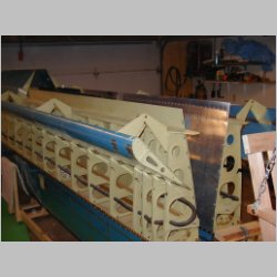
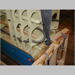
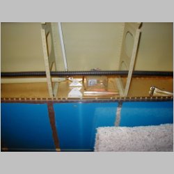
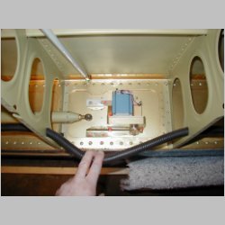
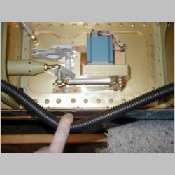
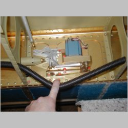
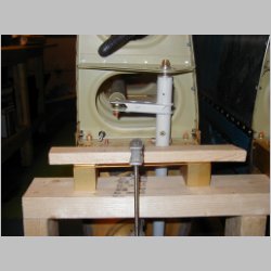
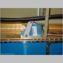
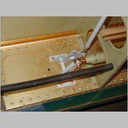
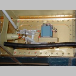
One thing that I did try to do for the rest of you builders is to take some good pictures of the TruTrak autopilot servo installation. I had many questions about that in the beginning, so hopefully I can clear it up for future builders. You'll notice below the TruTrak installation. You basically remove the lower bellcrank bracket from the right wing, and
replace it with the new one for the TruTrak. No additional holes to put in the spar. You also pull one of the 2 top bolts, because there is another bracket to support the servo that attaches there. One bit of caution....TruTrak will claim that the servo comes with all installation hardware...that's not true. You need to provide the bolts and washers. I didn't know what to purchase, so another builder, Bob Condrey gave me a list. (Thanks Bob)
You basically attach the new brackets with existing hardware, but then you need the hardware to attach the servo to the brackets. That's what's so ludicrous...TruTrak should supply that hardware, because it is completely connecting their components. Here's a parts list from Bob:
- 4 AN3-6H drilled head bolts, could also be fillister head screws.
	ALTERNATE #1: (GREAT solution!! I'm doing this:  Use 3 bolts
		NAS1801-3-20 (Fully Threaded. Then use locknuts)
	Alternate #2: (Worse...but ream out AP servo bolt holes and use
		long bolts with locknuts)
- 1 AN3-7A bolt (servo arm to rod bearing)
- 1 AN3-12A bolt (rod bearing to bellcrank)
- 2 AN970-3 area washers
- 2 AN365-1032 locking nuts
- 4 AN960-10 washers
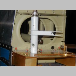
Most of the steps in this section were very straightforward, but I did find that you REALLy want to read ahead a page or so before you do any step. You'll save yourself re-doing things. Also, read in detail. An example is: If you look CAREFULLY, you'll see that when you bolt the aileron control tube to the torque tube brackets, you need to use 2 washers...even though the diagram shows only 1. (It does note 2 though) I had to pull mine apart and add the washer. You also want to pay VERY much attention when drilling for the "clocking" of the the torque tube collars for both fore and aft controls arms. There are 2 drawings, one for the right and one for the left. Make sure you know which one you're doing....and don't do them the same. (I didn't mess this up) Also, when setting the clocking, you need a 5/16" spacer. I found that the little piece of tubing that you cut in the earlier pages worked PERFECTLY for this.
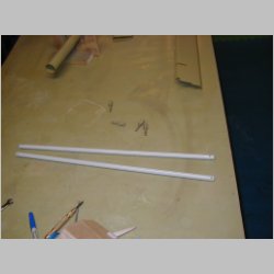
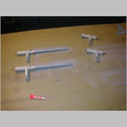
As for the long control tubes, Van's says, surprisingly, to prime them inside. They aren't much for priming, so to me this meant to really make sure to do it. I can tell you though that I wish I hadn't. I had those ends sliding in and out real nice when I prepped them, but after priming, I had to beat them with a hammer to get them in. And, I had alodined the aluminum tubes...which should have been plenty of protection from corrosion. I should have just left them. One thing that was WAY cool was that when building them, I put care into using the listed dimensions. It came out so well that when I had to do my measurement of something like 2 9/16" to the neutral position on those torque tubes (you'll see what I mean here) they were perfect. I did have to adjust my aileron pushrods by about 2 or 3 turns of the threads though when adjusting my aileron linkage. The jig works great for setting the neutral position. Nice to finally see what this was for too.
I also found a use for my handheld squeezer on this section, so I had to take pictures. The areas are too tight for the pneumatic squeezer, but a handheld with a longeron yoke works great.
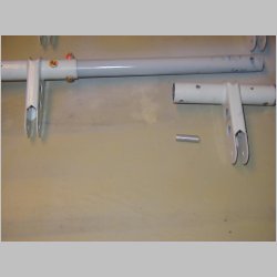
Oh, I almost forgot!! I found one very un-clear part of the plans. When cutting the tube pictured here, Van's does NOT have this in my version of plans. This control tube, or collar, or whatever they call it, is NOT talked about until it's time to start drilling holes in it. I had no idea how long to cut it, as it came as one rod, and I didn't know if it was supposed to only make 2 rods, or was going to be used for more parts. As far as I can tell, you just cut it in half....about 11", and it's never used for anything else. Stumped me for a while trying to find out where the step was to cut the tube.
The one thing that I had wanted to work on but haven't been able to accomplish yet is the Pitot Tube. I'm going full IFR, of course, so there's no way I'm using the Van's el-cheapo method of building the tube. I need a heated tube. I got my mount from Gretz Aero recently. Here again I wish it was JUST a little more complete. It turns out that they don't supply a little 5 or 6" lenght of Aluminum Angle AA6-.032-3/4x3/4. So, I have to order that. Also, a sensible and better mounting location is one bay outboard from the Aileron Bellcrank...just past the rib. Van's mounts it one bay inside from the bellcrank....putting it very close, and inside of the tiedown ring. Seems like it makes more sense to keep that rope a bit further away from the pitot tube, so I'm following the Warren Gretz instructions suggestion and moving it to the more outboard area. Problem is, Van's only provided enough aluminum tubing for their installation, so now I need to order a 10' length, or splice some plastic into mine. I'm going to try going all aluminum if possible. They do try to add some extra so the pitot can be removed easier, and suggest using a 6 or 8" lenght of aluminum or copper attached to the pitot, and then going to plastic, and leaving a service loop. I may go this route, but I'm still going to buy a roll of aluminum tubing and make sure that I run AL all the way to the bay with the bellcrank. I think I'll just wait until I get the actual pitot tube though, so that I can see it all before I order parts.
Well, onto the photos!
(All pics are clickable)
|
|
|
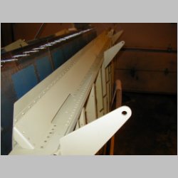
| Aileron Pushrods |
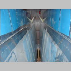
Aileron control tubes
(and elevator control tube) |
|
 |
 |
 |
| Dimpling,
and riveting the Aileron and Flap gap fairings |
||
 |
 |
 |
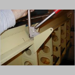
| Awesome, I get to use
my squeezer for once! |
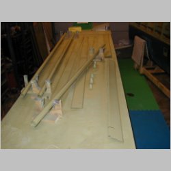
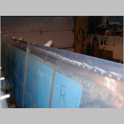
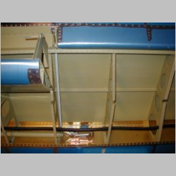
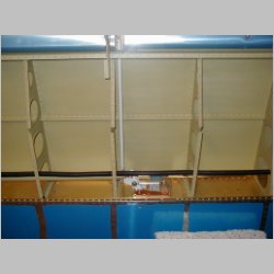
Stowing the
control tubes |
|
 |
 |
 |
| Throwing in
the pushrods |
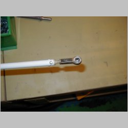
Pushrod end
install |
|
 |
 |
 |
| More
shots of the fairing install |
||
 |
 |
 |
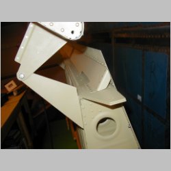
| Autopilot
parts |
Autopilot
parts |
New AP
brackets going in |
 |
 |
 |
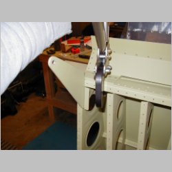
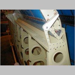
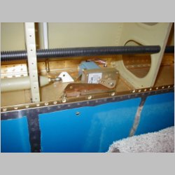
| New AP
brackets in place |
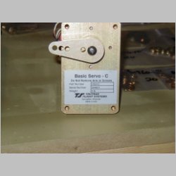
AP servo
mounting |
My AP servo
info |
 |
 |
 |
| All bolted
in place |
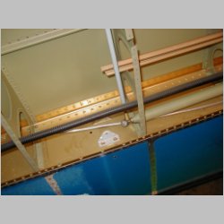
Torque Tube priming -
Note the spacer I used for "clocking" |
|
 |
 |
 |
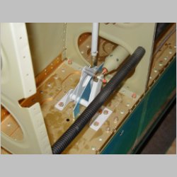
| Connecting
the lower linkage |
Another view |
Torque Tubes
installed |
 |
 |
 |
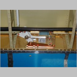
| A Closeup |
Attaching
the control tubes |
All hooked up |
 |
 |
 |
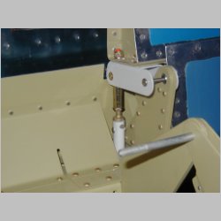
| Aileron
Pushrods outer end |
Looking at
the linkage |
Using the
jig for "Neutral" |
 |
 |
 |
| Another view
of the jig |
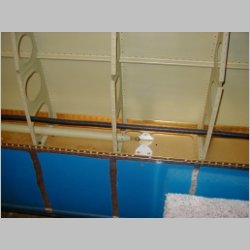
Align the ailerons to
the flaps when neutral |
|
 |
 |
 |
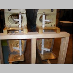
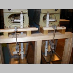
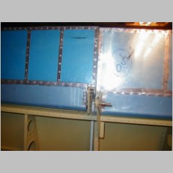
| Left side
bellcrank complete |
Right side
bellcrank complete |
|
 |
 |
|
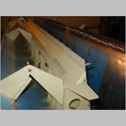
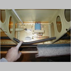
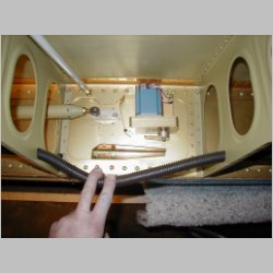
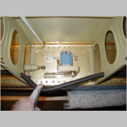
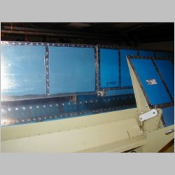
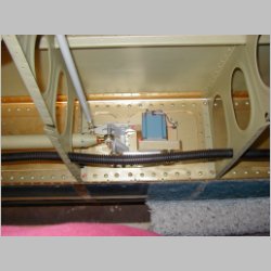
| Completed AP servo
and Aileron linkage in Right Wing |
||