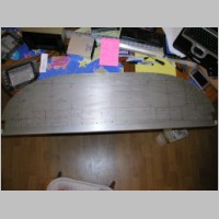
Laying out the Panel pre-cutting - Filling it with Radios
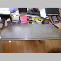
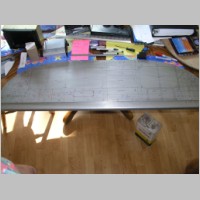
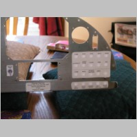
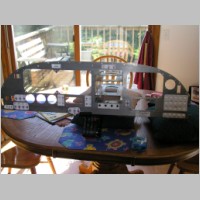
Sorry this jumps around a lot, but I got pretty busy with this panel. The first photos show laying out the panel for the instruments. I myself think there are a few EXTREMELY valuable things you should do when laying out your panel.- Make Stick-on fullsize photos of all your equipment and place them where you like them
- Have your power wiring (mine was an Aeroelectric Z-Diagram) complete before you start the panel
- Make sure you have your Load Analysis done for all your equipment. (This one is incomplete)
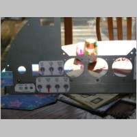
- Make your list of switches and lights and breakered items well before you get to this stage
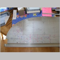
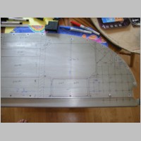
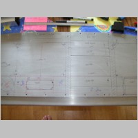
- Print out true-size switch layouts and stick them on where you want them too
- Draw everything in exact size onto the panel as below - Write dimensions on the panel
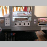
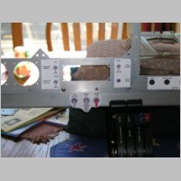
- As you're going along through the cutting process, doublecheck EVERYTHING
- Have your add-on's handy (i.e. Trim kit, Flap position system kit, ... )
- Know which throttle (3-lever or push-pull) you're going to have before this stage
- Cut carefully, and not oversized holes.
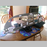
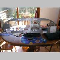
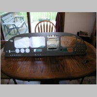
Another thing that MAY be critical at this stage is panel labeling. I plan to silkscreen on my labels. There are local places that will produce silkscreens for about $60, and with those you can produce very professional labeling. The issue is, you need to do this BEFORE you permanently install the gauges, and BEFORE you put that bottom support bar (I call it the switch bar) into the plane. So after OSH, I'm going to jam on that and get it done right away. We just ran out of time right now.
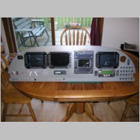
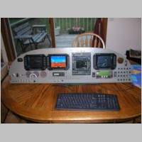
So far, none of the last pictures on this page are 100% complete. There are still a couple of indicator light holes that I need to drill. I don't have any good photos of the current panel, but come to OSH 2005 and it'll be sitting in SteinAir's booth #2030 in Hanger B. My engine will also be on display at AeroSport Power's booth.
As for the Load analysis and Z-Diagrams linked above, those are things that I've borrowed from others and modified for my wishes and equipment. I know my "essential" list of equipment is on the heavy side for the standby alternator I'm choosing, but I'm considering that I'll still have 2 batteries to feed this stuff with.
The load analysis might not be 100% accurate either yet, but it does give a good indication of the load that we'll be operating with.
Much more to come!
|
|
|
|
|
|
|
|
|
|
|
|
|
|
|
|