Cutting The Panel and Mounting Radios
Total Time Approx 16 hours for work on this pageCutting the Panel
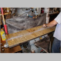
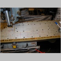
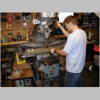
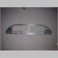
This weekend was INCREDIBLY productive, special thanks to my great friend Steve. Without him, this panel would have been much harder to prepare with such quality. My panel was originally sent out to a place that does waterjet cutting, which would probably be the ultimate way to get your panel cut. If you can provide a CAD drawing of the panel, it's pretty cheap to get a panel cut. $95 I think at Pacific Coast Avionics, and this waterjet job was I think going to be a couple hundred. Anyway, it's reasonable I think. Well, after waiting a couple weeks in line to get cut, it turned out the waterjet broke....ouch, and this panel needs to be ready for OSH 2005. (It will be on display at SteinAir's booth in Hanger B, booth 2030) So, having a great friend who also has a mill in his own garage (air conditioned, no less), I called on my buddy Steve to help me mill this thing out. We could cut everything except for the 45 degree cuts, since he doesn't have CNC machining.
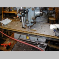
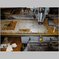
We bolted a 3/4" plywood board to the mill, and then used tons of screws to attach the panel, to prevent chatter. We cut without fluid, with a 1/4" bit, and it worked like a charm with no problems. The night before, I had taken the time to draw with very high precision, all of the instruments that were going to be on the panel. I had intended to do the whole thing in CAD, so we could just cut by numbers, but I couldn't round up all the CAD files for the instruments in time. So, I used all the available drawings to draw it by hand. As it turned out, for the most part my hand-drawn lines were accurate to probably 1/16" over the entire width of the panel....VERY good, but nothing compared to the mill, after it was set to run straight across the panel.
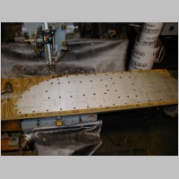
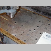
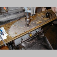
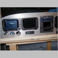
Each instrument, we started at a zero point. Just for future reference to others, I had forgotten to leave a tiny extra space between the 2 Chelton screens...so my drawing was tight together. As it turned out, I caught that mistake, and we added in a gap of .040 between the screens, which comes out basically PERFECT! I also left .8" between the Cheltons and the radio stack, for the 3/4" .063 angle to mount the radio tubes. I had previously trimmed back my ribs, which you can see HERE. Then, I trimmed the front flange a little bit up so that the rib wouldn't need any more clearance than necessary to the instruments below. I ended up with my Chelton screen holes .75" below the outer 2 ribs. The Left radio stack angle is exactly centered with the center rib, and the hole that matches with the rib is actually right through the center of the angle. Worked out perfectly, and gives added support. We cut the entire panel that way, everything we could. Couldn't get the square holes finished off with the mill, so I used a file for those. Works fine, and just takes a little time and care. Cut the corners of the 45's to join the vertical and horizontal cuts by using a dremel tool with a heavy-duty cutoff wheel. Everything was cut basically exactly to specs.
After the panel was cut, I trimmed the 45's, then filed everything. A test fit of the Cheltons showed that my 45 degree filing needed more work, so it was file, then deburr (to protect the Chelton) until they fit right. The Chelton requires screws no longer than .22" behind the panel, by the way, so probably need to use .25" screws...the panel in the RV-10 is made with .063 aluminum. After some filing, everything fit, but I used 150 grit sandpaper to make the square holes lose their file marks. I'll later finish sand them with 220 grit, and then scotchbrite them.
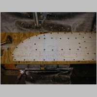
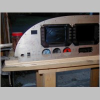
I did not cut the 4 holes for the round gauges yet, since I don't have them in-hand to verify hole spacings. I also didn't cut the switch holes, just breakers, because I didn't have switches to verifiy spacings, and I hadn't yet completed my switch/light/breaker listing. I have most of that done now and will post that later. Monday I'll verify some of those items and finish the drilling. Then it's time to polish it up a bit, prime, and paint. Then it's off to SteinAir to silkscreen and wire the thing. That will be a big learning experience for me.
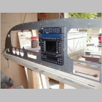
The WORST of the instruments in the panel is the TruTrak flatpack autopilot. They built it so that it only comes flush with the surface. It would look much nicer if it stuck out 1/8" or 1/4" from the panel. Perhaps I'll mention it to them at OSH....maybe they'll change the mold and give me a new front faceplate. :) (wishful thinking)
The Radio Stack
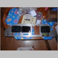
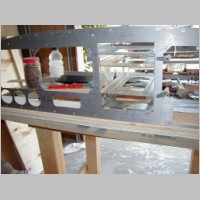
Cutting the Radio Stack was an intimidating process for me at first. Hopefully this page will help you out. The installation guides note to leave at least .040 between radios, so the locking latch will clear when you pull the radio out. I didn't know if I had to ADD space between the radios, or not....made confusing because they actually stamp dimples in the upper radio surfaces (and lower on some) to provide clearance between other equipment. I didn't know if I needed the dimple spacing AND the .040, or not. Turns out you don't need anything but the dimple spacing. We measured something like 7.575" from the table to the top of the stack when sitting on the table, so we cut it to 7.600" (I think that's the right number...bad memory) We gave it a hair more, but not much. This turned out to be 100% as PERFECT as we could get.
As it turns out, you don't need to add that extra space where there are dimples, but you DO have to remember that the bottom radio requires a way to have it's latch clear the panel opening. So, you do need a tiny bit of extra. The bezel on my audio panel hides any gap on top, and the transponder on the bottom makes the gap invisible on the bottom. The hole was cut to EXACTLY 6.25" width. Some radios showed 6.3" required, but so far I just don't see it (with 1 exception that I'll mention later)
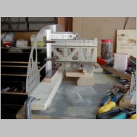
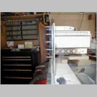
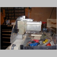
For mounting the tubes, first I screwed the panel to a board, that was clamped to the table. Then, I cut some aluminum 3/4" x 3/4" x .063" angle for the side supports for the tubes, and clecoed it in place with clamping clecos right on the edges of the radio stack. To get the radio tube near the hole, I blocked the front of the radio tube for the transponder so it was near the correct height, and I blocked up the back of the radio tube so that it was approximately perpendicular to the panel. I added a shim below the transponder to give the clearance for that latch. I used an Aviation Grade, calibrated, Popsicle stick that was .063" thick that I obtained from the Aviation department at Wal-Mart. I used a stack of them until I got the proper height in the rear too.
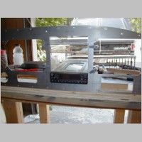
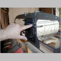
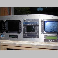
At this point, all of the mounting tubes are stacked up, between the rails. I stuffed in all the radios, tested that I could slide each one in and out individually, and they all fit perfectly through the hole in the panel. The SL-30 did have one hangup. You'll see the photo where I'm pointing to a screw on the bezel. That screw sticks out far enough to make that ear on the bezel not fit into the panel. So, I VERY slightly notched where the screw goes through the panel, and then deburred the area by the SL-30 down a tad, to allow that ear to pass through snugly. At that point, the entire stack fit perfectly.
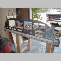
Then it was time, since I had the overall width down with the tubes in place, to drill and cleco the mounting rails in place to the panel. I'm told it only takes 2 or 3 rivets per side, but I used 2" spacing and put about 5 per side, countersunk AN426AD3-4.5 rivets. They countersunk PERFECTLY to the panel. Now the rails were tight, and the tubes all fit. Some real snug, some less snug...too bad there isn't a tight-tolerance standard between brands, but I needed NO shims on mine. Now is the time to stock up on some screws. You need a pile of #6 flathead screws, AN365 #6 nuts, and #6 washers. I thought the transponder needed #8's, but AFTER drilling the holes in the rail, I found out the screwhead didn't recess enough, so, I countersunk my mounting tube a little extra, and then began with #6 flathead screws for the other trays. I think you need 3/8" and slightly longer screws (maybe up to 1/2" or mouting most tubes. Get a variety of #6 screw lengths before starting....maybe 25 packs of each of 3 or 4 sizes.
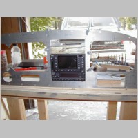
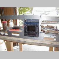
The process to finish the tubes was: Put all the radios below and including the one being mounted, into their tubes. Make sure that the radio bezel was flush with the panel WHEN PUSHED IN. Yes, when you pull the radio out against the latch, you'll get a tiny gap between the bezel and the panel, but, if you try to fill that gap by securing the radio full rear, that latch may not operate smoothly. Mark the tube position on the rails, so you can keep the front to rear spacing after you yank the radio and disturb everything. Then mark the screwholes with an ultrafine sharpie from the inside the tube. I drilled my holes with 12" long #40 drillbits to start, since you can flex the bit into that area. Then, I used larger bits on the drill to enlarge the hole to the right size for a #6 screw. Then deburr the holes, stick the tube in, and scew the tube to the rails with the nuts on the outside.
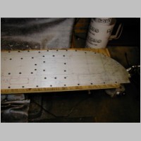
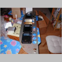
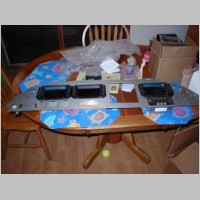
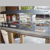
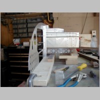
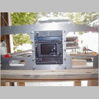
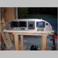
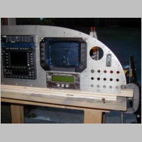
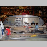
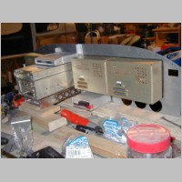
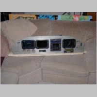
With the radio stack done, I checked our spacing on the Chelton holes that were drilled 3/32", and they matched the Chelton's perfectly. Then, I final drilled those holes for the #10 screws (.25" length) that the Chelton uses to mount. At this point, I just wanted to see it all in the panel, since I don't have every last breaker and switch here. So I secured everthing with only a couple screws. Then I shot the photos. Everything looks great to me. I weighed the panel, as shown in the final photos, including the board mounted under it. It weighed 33.5lbs, but you have to subtract a few pounds for the board....it's thick plywood.
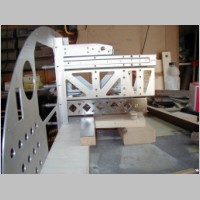
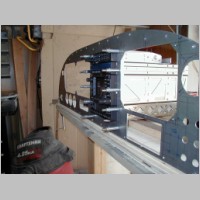
A couple of points: #1, Cheltons and other EFIS stuff make panels easy to build, since they have less "stick-out" in the rear. The radios will have to penetrate the sub-panel, so that means a hole to cut and reinforce there. The more glass you have, the less going thru the subpanel you'll have.
#2, similar to the above, I have the suggestion that you carefully choose your radio stack locations. If you scatter radios around your panel, that means you'll be doing many more aluminum angles to mount the trays, and many more oddball penetrations thru the subpanel, and have many more opportunities to have radios hit ribs, requiring you to cut back the ribs.
This panel, while VERY full, was very easy to accomodate behind the panel. See the photos below for the proof.
All-in-all, I wish I could have saved the many hours and had the waterjet cutting, but, doing it myself allowed me to do some last-minute changes, and save some cash too. 8 hours to machine the panel, (including pizza break), and probably 8 hours to file, sand, and drill it, and mount the radio stack. I DEFINITELY think I've found my calling as far as plane building goes. I'm NOT a fan of many of the other building jobs, especially fiberglass work, but I absolutely love this type of work, and wiring. If only there were tons of -10 builders by me.....I'd trade them panel building time for their help doing body work and some of that garbage.
More to follow, but don't forget to check out SteinAir's booth 2030 at OSH, in Hanger B, and see this panel!
|
|
|
|
|
|
|
|
|
|
|
|
|
|
|
|
|
|
|
|
|
|
|
|
|
|
|
|
|
|
|
|
|
|
|
|
|