Added 10/16/2005 - Updated 10/22/05 - 1165.5 approx. Total hours (1006.2 By Me)
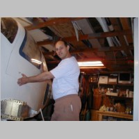
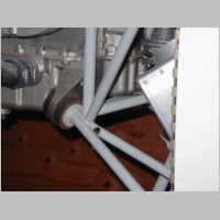
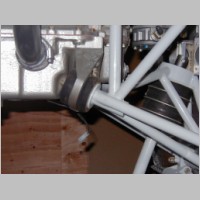
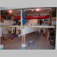
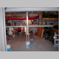
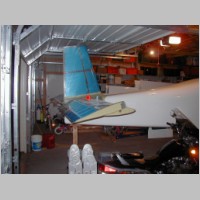
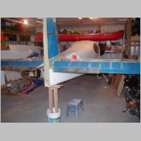
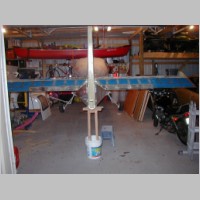
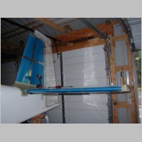
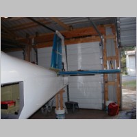
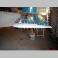
Well, after some prompting from another RV-10 builder, I finally asked Van's the question..."is my .100" approx clearance between the engine and engine mount below the rear sump enough, or not?" Unfortunately Bruce had bad news for me. They really think you need about 1/2" there. They suggested I either have it cut and re-welded locally, or I send it to them and they'd do it. They were very good about it and Scott actually said he'd prefer it if I'd send it back so they can analyze the situation by putting my engine mount in their jig and matching it up with their test engine case. So, after some really pain in the butt packaging (about 3 hours) and $50 in shipping, I got it out via FedEx. You'll hear more on that after I get the engine mount back. Luckily I hadn't hooked up any wires or cables yet, so it only took about 20 minutes to yank the engine and mount. As you can see, the plane is now painted and using my cement filled tail stand for support. UPDATE 10/22: See my Engine Mount Mod page for an update!
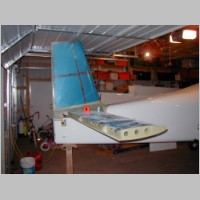
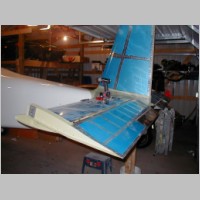
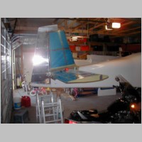
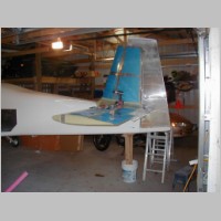
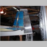
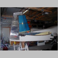
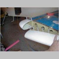
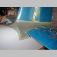
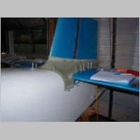
To continue preparing for paint on the tail surfaces, I've been working on empennage fairings. Unfortunately this week was a bit on the lesser productive side. I did get all of the fairings on and drilled, but not all riveted yet. I have the 3 tips that need to have that closeout panel made out of fiberglass, and I haven't got any foam to make the foam ribs to form them around.
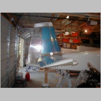
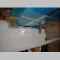
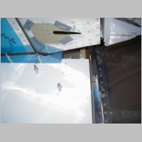
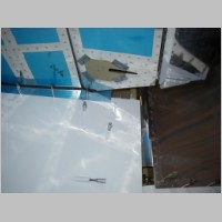
The alignment of my empennage parts went real well. I screwed in all of the rod end bearings very carefully to the exact specifications and I didn't have to adjust a single one of them after that. Everything swings very smoothly and freely. The Elevator travel is EXACTLY the 25 and 30 degrees required, and the rudder is exactly the 35 degrees required. I adjusted my elevator pushrod end bearings to the exact specs and even the 91.4 degree bellcrank angle came out perfect. Vans did an EXCELLENT job on this area of the kit. The only trouble I had is that when I attached my HS, you start by drilling 4 of the rear bolt holes. For some reason, my front HS mount brackets must not have been sitting perfectly flat on the deck, because one side was about 1/16" above the deck. I ended up bolting those down, and then going back and adding a tiny bit of oval to the holes on the rear to allow it all to sit perfectly horizontal. It now looks very good. Previously, at the tips, the tip to ground measurement was about 1/2" different from one end to the other....or 1/4" off per side. Not too bad, but I wanted better.
Trimming the fairings for the front of the rudder and HS were the hardest, but working slowly they came out great. Just take it off little by little.
Previously I hadn't done anything with the elevator trim control unit, so I started assembly of that as well. This week I hope to drill my wingtips for strobes and my LED Nav lights, and install my Bob Archer Nav antenna, finish the closeout panels on the HS and rudder tip fairings, and then finish prepping the tail surfaces for paint.
|
|
|
|
|
|
|
|
|
|
|
|
|
|
|
|
|
|
|
|
|
|
|
|
|