AHRS Mounting, Door Latches, Spinner, New
Headliner, Top Cowling
Added 9/5/2005
- 945.4 approx. Total hours (848.5 By Me)
Another
mass update of photos from the past few days. This was Labor
Day weekend, and I decided to spend it in the garage getting this done.
I'm starting to feel like things are moving along pretty
well, and I just may get it painted within the next month.
Once that happens, what I would consider "the fun part"
should begin....wiring, engine hookups, and that sort of thing.
See below for more details.
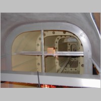
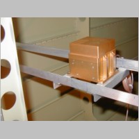
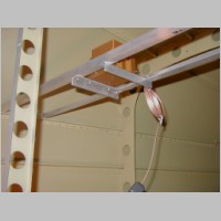
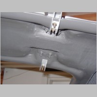
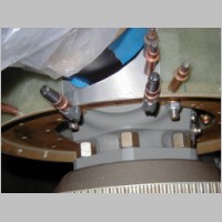
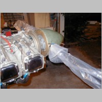
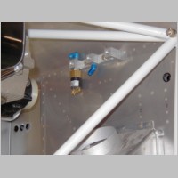
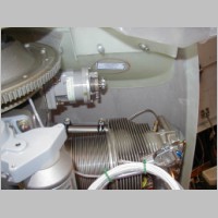
AHRS Mounting
After asking a couple questions to the group and to Direct2Avionics, I decided on my location for mounting the Crossbow 425EX AHRS. I made a shelf out of .125 Aluminum angle and ran it between my longerons behind the baggage wall. I have already heard a comment from another builder who put it on the floor by the battery that a tow bar interfered magnetically, so I wanted to get it up and back a little ways. It seems ver stable, and I also plugged in the AHRS to my PC and booted it up. The heading seems to read very well. I think this will be a good location. I'm planning to mount my WSI and 2 GPS antennas just above it in the roof of the tailcone. I am trying to ditch my WSI standard antenna for one that combines the WSI and my GNS480 into one antenna. That will reduce the clutter on top of the canopy. The GPS antenna supplied by Chelton for the AHRS is very small, so that one I don't mind too much. The Chelton antenna requires a 4" ground plane. I don't believe the Garmin antenna does. Can't remember right now.
|
|
|
Door Latches
I have been continuing on the door latches and now have them operating. I did find an issue with the plans on page 45-15. If you do everything per directions, you will be mis-drilling those 4 UHMW blocks. Look at the drawing and it tells you to shim one side .040 so you get a 3.4 degree hole. Notice how the profile view of the part shows the angle of the hole. Now, notice if you shim that side, you will have the hole angle wrong. Also, they want those 2 points centerpunched and then drilled on the canopy to the inside of the door frame. If you tried to line up the hole after mis-drilling that part, those holes would be on the outside of the door frame. So, pay attention and think this through slowly. The blocks do need that angle, to keep the pin running down the door properly. Just don't drill those 2 holes or centerpunch them until you've taken a 7/16" drill bit and stuck it through the part and the hole in the doors and madesure it slides in the proper direction.
Another builder also gave me a tip that I noticed but had passed off until now. I think it's the rear pins, but anyway, the pins may be too long. When you retract them, you want them to retract most of the way into the UHMW blocks in the door itself, so that it doesn't scrape the door frame when you open and close the door. Now, picture how it will be when you have the 2nd UHMW block attached to the door. You'll need an additional 1/4" clearance now to shut the door, so if the pin is too long, it won't go, and it's a much easier thing to shorten when it's not on the plane. So, fit the parts, make the latch work, then verify the pin length before pinning and safety wiring it on.
I also installed the lift cylinders. Make sure you get the revision before you do the lift cylinders.
A note about revisions: You cannot trust the plans that come with your kit, so verify your plans revisions!!! I bought my FWF kit on 5/25/2005. My plans on page FF1-4 were dated something like 1/26/2005. I had almost called to complain to Van's about a missing fitting, but as it turned out, the plans had changed on 2/22/05, and now that fitting was no longer required. Don't ask me why when I purchased plans on 5/25, 3 months after the revision, they didn't send me a complete set of plans with the revision in them. This to me is another spectacular example of where customer service should absolutely be improved. In addition, it would be no major deal for any organized company to send out email notices to their RV-10 builders to notify them of plans changes.
|
|
|
|
|
|
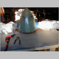
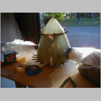
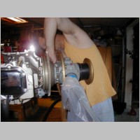
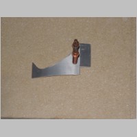
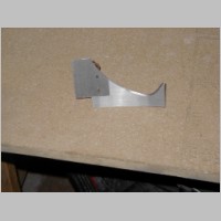
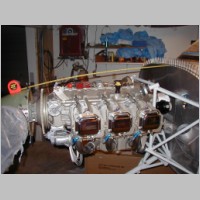
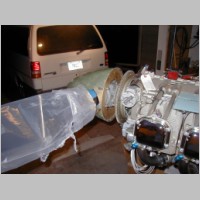
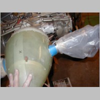
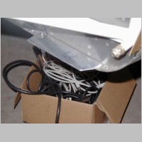
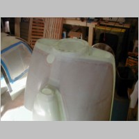
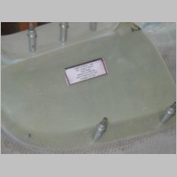
Spinner, Continued
The spinner was one of the more fun things to work on. Don't ask me why, I just don't know. it goes together well, and mine didn't require trimming on the rear side. I made a cardboard template per plans, and trimmed the holes for the prop blades. That came out excellent. The only catch was when I taped my cardboard template to the spinner, the bottom end of the cardboard pieces came together a bit, so I had to take off some additional material towards the rear of the spinner slot. I did the rough cut with the cutoff wheel supplied for the windshield, and I did the trimming to the line with a 1.5" drum sander on a die grinder. It was pretty quick and easy to get it to 1/16" gap around the prop. I used a Craftsman Strap wrench to turn the prop and rotate it to check for hole interference in the spinner. I think the setup with a couple boards would work easier, but the strap wrench seemed to do OK too. (This is a RUBBER strap wrench I'm talking about, not a chain wrench!) I installed the pop onto the engine before I did the trimming of the hole during rotation. That gave something more substantial to hold the prop when I twisted it. Note that the prop will only mount in 2 orientations. (mine is the Hartzell Blended Airfoil)Making the gap filler wasn't too bad either. I used some scrap .063 and made another cardboard template. Somehow it came out fantastic with not too much work.
The only part about the spinner that I question is the hardware supplied. The plans call for round head screws with nylon washers underneath. The hardware supplied is countersunk flat head screws and Tinnerman (sp?) washers under them, countersunk into the spinner. Well, my spinner didn't reach all the way to the absolute rear of the backing plate, and when drilling nutplate holes on the rear edge of the spinner, my holes are close enough to the edge of the spinner. If I were to try to use those washers, they would actually stick out PAST the edge of the spinner a tiny bit. That means the countersink is very close to the edge too, and I don't trust that structurally. I think I'm better of not using the supplied hardware, but using the stuff listed on the plans. I actually prefer the look of the round head screws to those ugly washers, and I think it'll be better structurally.
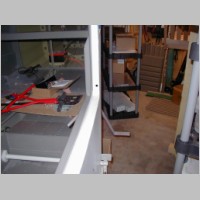
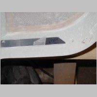
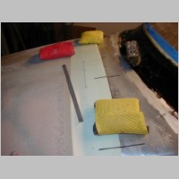
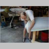
There's a couple of shots below with tape measurements being done. If you need those numbers, here they are:
Spinner plate to top of firewall = 41-9/16"
Spinner plate to middle of angled firewall = 41-3/4"
Spinner plate to top of non-angled firewall = 42-1/2"
|
|
|
|
|
|
|
|
|
|
|
|
|
|
|
|
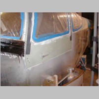
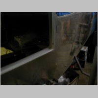
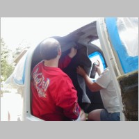
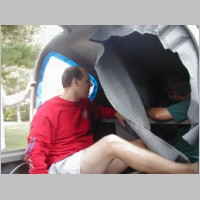
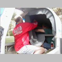
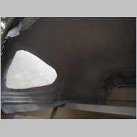
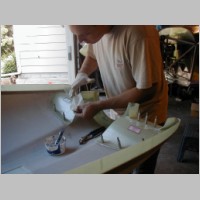
New Headliner - Much improved!
This time I'm VERY happy with my headliner. That 1/4" foam backed stuff I used before really sucked, so you might have seen how I ripped it all out. This stuff is a grey fabric, which is available from Abby at Flightline interiors, Cleaveland Tools, or the Orndorffs. It costs probably double what the foam does (triple when you consider I ripped out my foam. ;) ) but looks much nicer. I bought 7.5 yards of it, and set to work installing it. Having now done this after the canopy and windows are installed, I really don't think it's a big deal. Ideally, you would install with the canopy off and upside down, but then you'll have to deal with keeping the window glue off the canopy. So, it's a trade off...unless maybe you did the windows before the canopy is fitted to the plane, and then did the headliner. Don't forget the paint. It's a nasty sequence of events. The glue used is 3M Super 77. Great stuff...better than the stuff I used on the headliner before too....it goes on clear and is repositionable for a short time.One tip: I covered the rivet line below the rear windows with 3/16" thick open cell foam. It hides the rivets really welll.
Stay tuned for more info on the interior...I've got a pleasant surprise coming.
|
|
|
|
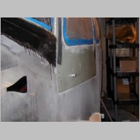
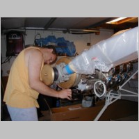
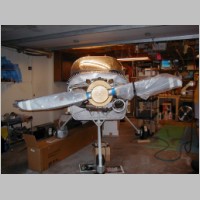
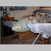
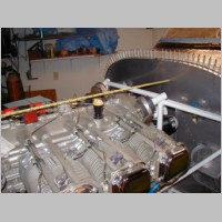
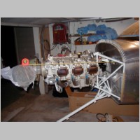
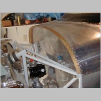
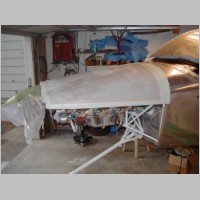
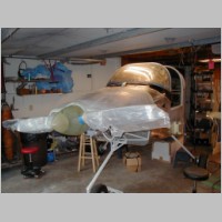
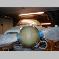
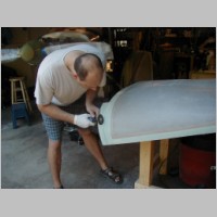
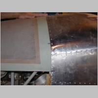
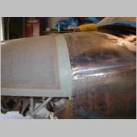
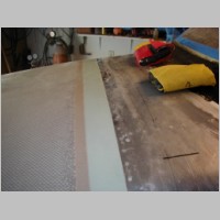
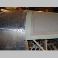
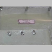
Top Cowling
Before starting my top cowling, I committed myself to my attach plans. No camlocs for me. I decided to save my pennies, even though they'd be great to have. Instead, on the lower end I am using a .063 aluminum plate, with a .030 shim. The thickness I have for the existing edge varies between .070 and .085, so when you add the .030 to that, you usually see an average measurement of about .100 or .105 up to the point where my .063 plate is. That plate will contain the nutplates used to attach the lower cowl. On the cowl side, the thickness is about .050, and I had some .050 sheet laying around from OSH 2005, so I will be bonding inside the cowl a strip of .050, just used so that I can screw through the cowling without worrying about cracks. That should make my cowling thickness the same as the fuselage build-up.Trimming the cowl is both easy and a pain. The first step, just using a straight edge and measuring where to trim the excess, is one of the least favorite. It took a bit of sanding and removing globs from inside the cowls before they'd fit together at all, and I did find that even though I think I did a good job on the straight edge, there are some minor inconsistencies in the cowl so it's easy to remove too much material. The sides apparently do not fit together inside one another either....so don't expect them to. At that point, sticking it on the plane was a breeze and it immediately looked much cooler!
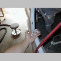
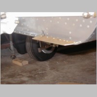
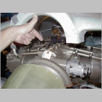
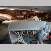
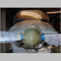
Now, notes about fitting it. Use .125" shims between the nose and the spinner to hold that gap. Then, you'll see a photo below where I'm pointing to the engine hanging bracket. I adjusted mine during the cowl install by moving it up and down until it held the cowl at the perfect height...that way I didn't have to hold it by hand. What is the perfect height? Well, the plans don't tell you a key tip that other RV's and Glastars apparently have in their plans. The engine mounts sag after 100 or 200 hours, so you want to mount the spinner to be maybe .125 to .250" above the cowl That way when the engine mounts do break in, the spinner flows smoothly into the top cowl. It still looks great when new, too, but it'll supposedly look perfect later. Make sure you have all of this set right before you draw the lines onto your fiberglass. What? Oh yeah, let me explain. How you trim the cover is to draw a line exactly and precisely 3" from the front edge of your fuselage skin, back onto the fuselage top. Make it perfect. This allows you to lay over about 2" excess material on the cowl, right on top of your fuselage, and then measure forward 3" from your line and transfer that to your top cover. In theory, if you then cut right on that line, you'll have a perfect fit to your fuselage. Make sure you have all of the up/down and left/right stuff just right before you transfer this line though. I didn't actually go through the plumb bob thing in the plans. When I laid my cowl on top and did some other measurements, including cowl to floor, I could tell right away that I was within about .1" when I had it so that it "felt" right. Then I tweaked it a little until it really measured out well and had a great balance shape to it. I forsee no problems.
The good news is, when I trimmed my top cowl, it fit almost perfectly! This should be something that I eventually will really be proud of, if it keeps up. You'll see some photos below.
Then comes gluing in the "ramps" inside the air inlets. These are simple to do as well, but be aware that your ring gear will interfere once you have the ramps on, and your prop governor will too. I'm still allowing my fairing filler to harden fully, so I haven't cut my holes for those things yet, but I know I'll have to. I only wish I knew if there was supposed to be something particular done around the governor...it says nothing about this interference in the plans.
|
 \\ |
|
|
|
|
|
|
|
|
|
|
|
|
|
|
|
|
|
|
|
|
|