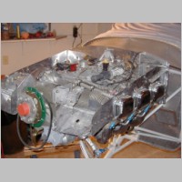
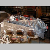
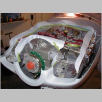
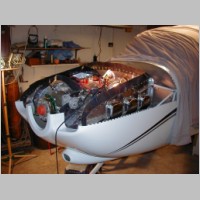
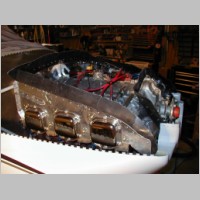
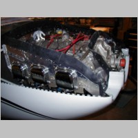
Engine Baffling
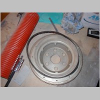
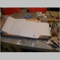
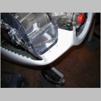
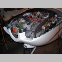
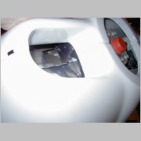
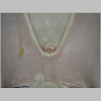
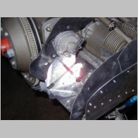
The baffling itself takes a fairly long time...probably over 40 hours for most builders. Some of the stranger items to install are those threaded rods that connect and hold the lower edges of the fore and aft baffles around the cylinders. They were a real pain to get oriented so they don't rub the cylinders, or the oil return hoses.When I did the rubber seals for the baffles, I had a good idea pop up... The plans say to use cardboard or paper for templating the harder pieces so you don't waste rubber sheet. I took it a step further. There was a 1/16" rubbery foam shelf liner on sale for about $3 at the home store, and it was 12" wide and 7' long. (I got white, seen below) I used that to template each rubber seal, and I taped them in place and test fit the cowl repeatedly until everything was just right. I took the starter gear plate off during the baffling stage as it makes it MUCH easier to see some of the test fits of the front seals.
Oh, as for trimming the baffling, about the most frustrating time is when you test fit the cowl, over and over again, trying to get that 3/8-1/2" clearance all the way around. It takes a looooong time.
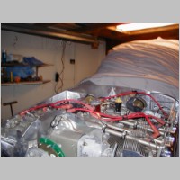
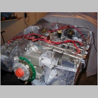
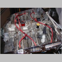
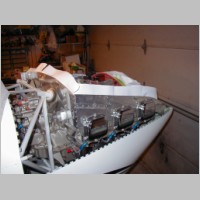
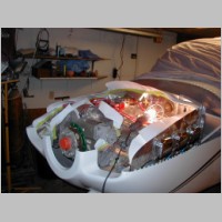
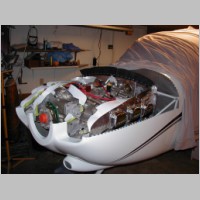
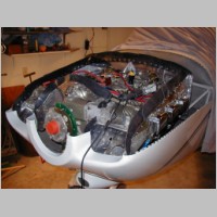
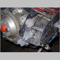
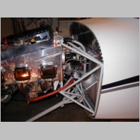
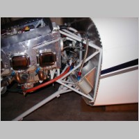
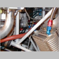
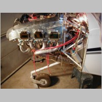
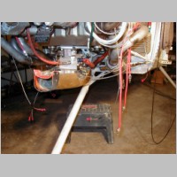
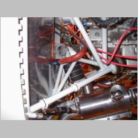
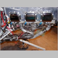
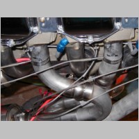
I took a few minutes to try to lay out my Lightspeed Ignition harness wires. It took a little playing, as with a fuel injection spider on top of the engine, and the ignition coils, there's not much room to move things around. But, I came up with a good routing. I also found that Bart at Aerosport had saved me a hassle and already installed the magnetic pickups into the front ring gear...Thanks Bart! Some of the latest photos even show my Reiff Preheater installed. That was a pretty easy install too, and they seem like they'll heat the engine up very well for me.
|
|
|
|
|
|
|
|
|
|
|
|
|
|
|
|
|
|
|
|
|
|
|
|
|
|
|
|
|
|
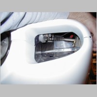
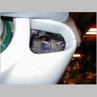
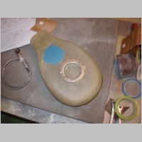
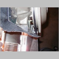
Filtered Air Box Install
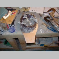
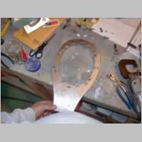
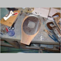
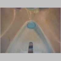
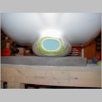
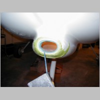
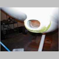
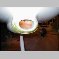
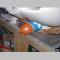
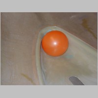
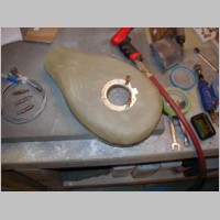
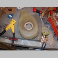
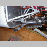
The FAB is another one of those not-so-fun items. The directions are OK, but poor by RV-10 standards. Too bad they just list the steps in text, and not with better pictures. The cutout on the side for the mixture lever was kind of a pain, but after improvising a bit, it all worked out. One thing I'm still not 100% comfortable with yet is how much to trim off the nose of the FAB. I think I have it OK, but with the seal on front, putting on the cowl isn't the most fun thing to do. For now though, I'm just going to give everything a try.Forming the air inlet nozzle was a good/bad mix. On one hand, it's a real pain to have to do it. The directions aren't all that clear, and in my case, I had the cowl already painted, so that makes it a hassle to have to repaint too. On the other hand, for as much of a pain as it is, they really have kind of a genius method to doing it. You stick an easily trimmable foam block, stuffed in from behind and glued in with bondo. Then you cut with a hacksaw blade so the block flows smoothly into the FAB. Then, you lay up some fiberglass/epoxy strips into the hole, and inflate a balloon. When you're cured, you have a nice nozzle and you can add glass to the inside too. That's where mine went a little astray. My nozzle didn't go back at the proper angle on one side, so I ground the edge out and reglassed it again, this time putting pressure with some rolls of foam (used above in the baffles) wrapped with wax paper, to get the proper angle. Then after some fairing filler, it came out fine.
One MAJOR note about the FAB alternate air bypass valve. Do your own research, but I believe that in fuel injected engines, you don't need to bother with the carb heat, so that saves a bunch of time if you don't install that. Another huge time saver is this: There is an OCT 2005 Service Letter from Vans....they have problems with their magnetic latch design, and they offer a free retrofit or different install kit. The new kit just uses a guillotine type blade valve, that once you pull, you have to re-set on the ground. It is a very easy install, and the entire FAB shouldn't be quite as bad if you go this route. I also painted my FAB gold, to match the engine (I'd avoid black to avoid picking up lots of heat) and added the drain tube.
|
|
|
|
|
|
|
|
|
|
|
|
|
|
|
|
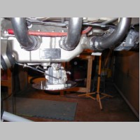
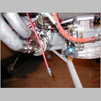
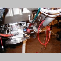
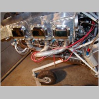
Engine Controls - Fuel/Oil Lines - Exhaust - EGT/CHT Probes
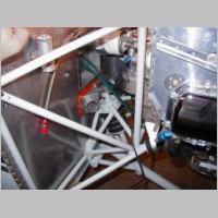
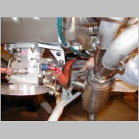
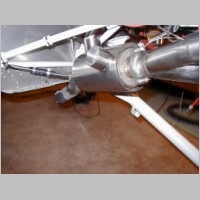
The engine controls have their own story.... In my case, I have the 3-lever controls, which have some plans updates in sections 31 and 41 for mounting the lever....too bad I didn't have these before I did those steps. I didn't have anything but the standard plans in the FWF kit though, so I figured it out on my own. The control cables went OK with a couple of exceptions. #1, You probably want to think ahead before you drill those 3 holes 5/8" for the cables. The standard method of doing the firewall passthrough kind of sucks, to say the least. A passthrough of a major cable with just a couple snap bushings?? I wanted better, so I bought the aluminum eyeballs....Scott Schmidt was my first view of those. They're $30 each, but in my opinion they're worth it. The problem is, I already had my 5/8" holes drilled, so I put 2 eyeball holes into the outer 2 holes with a unibit...but the holes ran into the center hole and my firewall got all messy. The 3rd hole I put below those two. Well, with the firewall holes bent up, I decided to get some stainless sheet from a local sheetmetal place and make a patch for that area that I could rivet in, and then drill my fresh holes in the new plate. That worked much better.Problem #2 is that after all the work to get all 3 cables in place, I find that I have less than 2" of cable travel for my throttle cable. The problem is, I need about 2-1/4 or 2-3/8" before it will actuate my throttle lever fully open to fully closed. So, measure your cables before you install them. Van's claims that all their cables are about 2-3/16", and they don't know why mine is the way it is. I just want to get it swapped out so I can move on with the item.
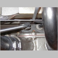
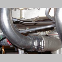
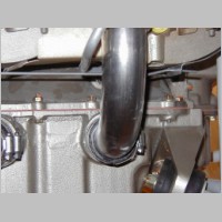
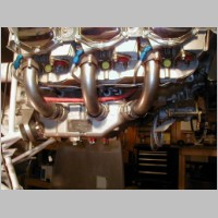
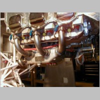
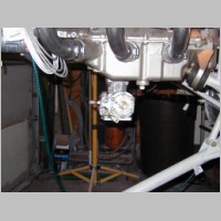
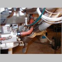
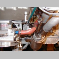
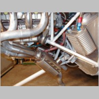
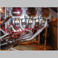
The fuel and oil lines went pretty well too. One tip: If you use the vetterman's exhaust, reverse your fuel line that goes from the pump to the servo. The 90 degree should be on the servo end. The issue is, you won't have clearance from your vetterman exhaust if you mount the fuel line the recommended way for the old exhaust. Also, don't bother making that hanger that is made from strapping metal....you don't need or want it with the Vetterman exhaust.
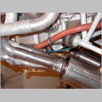
The vetterman exhaust goes in pretty well. I don't quite know how it'll seal, since the slipjoints aren't clamped in any way from what I can tell, but it seems like a good system. The brackets that hold the sections together are a very nice feature. As far as assembly, since there aren't currently any plans for me to refer to, I looked at Doug Peterson's kit #009 photos at: http://members.cox.net/rvator/id53.htm
This turned out to be a fair way to go. Doug did a good job, and his photos help a lot even without much instruction. One very key item for me was this: At first, I bolted on the stacks and then tried to attach the lower half to them. That was very frustrating and didn't go anywhere. Then I remembered Dougs note about doing "pre-assembly". This helped a LOT! After a pre-assembly off the engine, the stacks bolted up right away. Also, the manufacturer labled the parts with the stack number on both halves, right next to eachother, so you know the orientation really well. The only issue I still have that nags me is that after doing the lower hangers, I can see the possibility of the clamps slipping or the exhaust rotating a tiny bit and having a pipe contact the cowling or something, but the chance seems at least fairly remote so I'm moving on.
The oil lines, oil cooler, oil breater, and most other lines were no-brainers if you follow the plans.
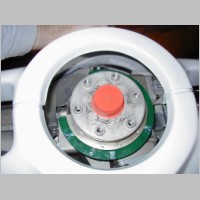
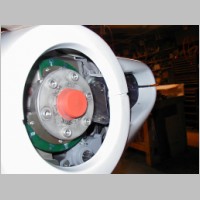
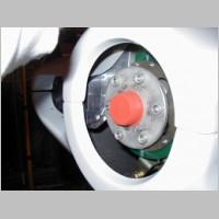
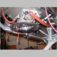
I also installed my EGT and CHT probes for my Grand Rapids EIS 6000 (Chelton Integrated Model). And installed my Mag Harness. A couple of us wondered what's the best way to tell how the mag harness goes on to the mag. Here's what I found:
If you pull the harness off, you'll see that of the 3 screw holes, only one of them is centered between 2 plug wire holes. Then, if you look with a mirror at the back of the mag, you'll see the holes are the same way, so you know which hole on the cap matches the hole on the mag. It does look like it would be slightly possible to get the screws to thread into the wrong holes, but looking at the screw holes makes it obvious which is right. Also, my mag harness has a "Left" or similar label that just happens to be on the outer left side of the mag, right by plug number 1. So when I look at the mag from the side, I see that label.
One Last Item... The bolts that hold the FAB attach plate onto the fuel injection servo. Vans warns you to safety them, but they're not drilled-head bolts. They also provide some cheap clips you can use. Remember that they are 1/4-20 coarse thread bolts, so they aren't your average AN4 bolts. I decided to use a fine drill to drill the heads and then safety them. It wasn't hard, and they drilled fine if I went slow. I don't know what size bit it was, but it was probably .040 or a tad bigger.
My last tip: Order some MS21919 size 14 clamps. There are a couple of tubes that are larger for the engine mount and you might want them for putting hangers for cables on. I'm going to order mine tomorrow.
|
|
|
|
|
|
|
|
|
|
|
|
|
|
|
|
|
|
|
|
|
|
|
|
|
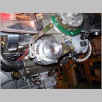
Alternator Install
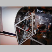
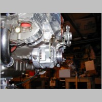
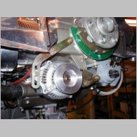
This is a continuation of the earlier section the Plane-Power Alternator. They came through as promised. With my tip to them about needing the bend in the slider bracket in a different place, they specially ordered and contracted a few HUNDRED new arms to be made just for use on the 540 series engines. The new brackets came, with a brand new 70A alternator and all accessory items and electrical harness. I bolted it right up, and it fit with no baffle mods. So now I'm ready to go with electrical power. Next year, if/when they come out with their vacuum pump pad standby alternator, I'll be adding that too.
|
|
|
|