Alternator Misalignment on IO-390
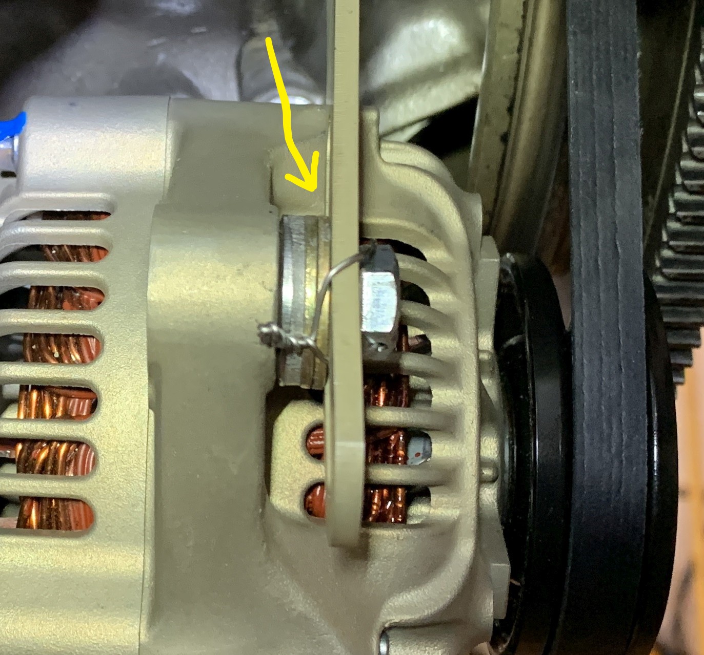
This should help to show the misalignment of the alternator pulleys using the standard p/n 403-315-2 Alternator Boss Mount Bracket. I also tried the 403-301-4 bracket, but that moves the alignment too far and then the alignment is off on the other side of the pulley.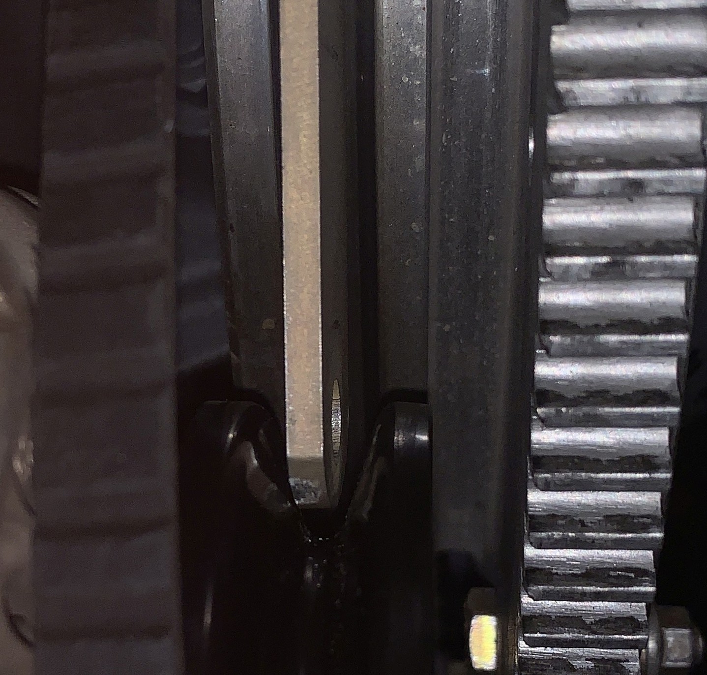 |
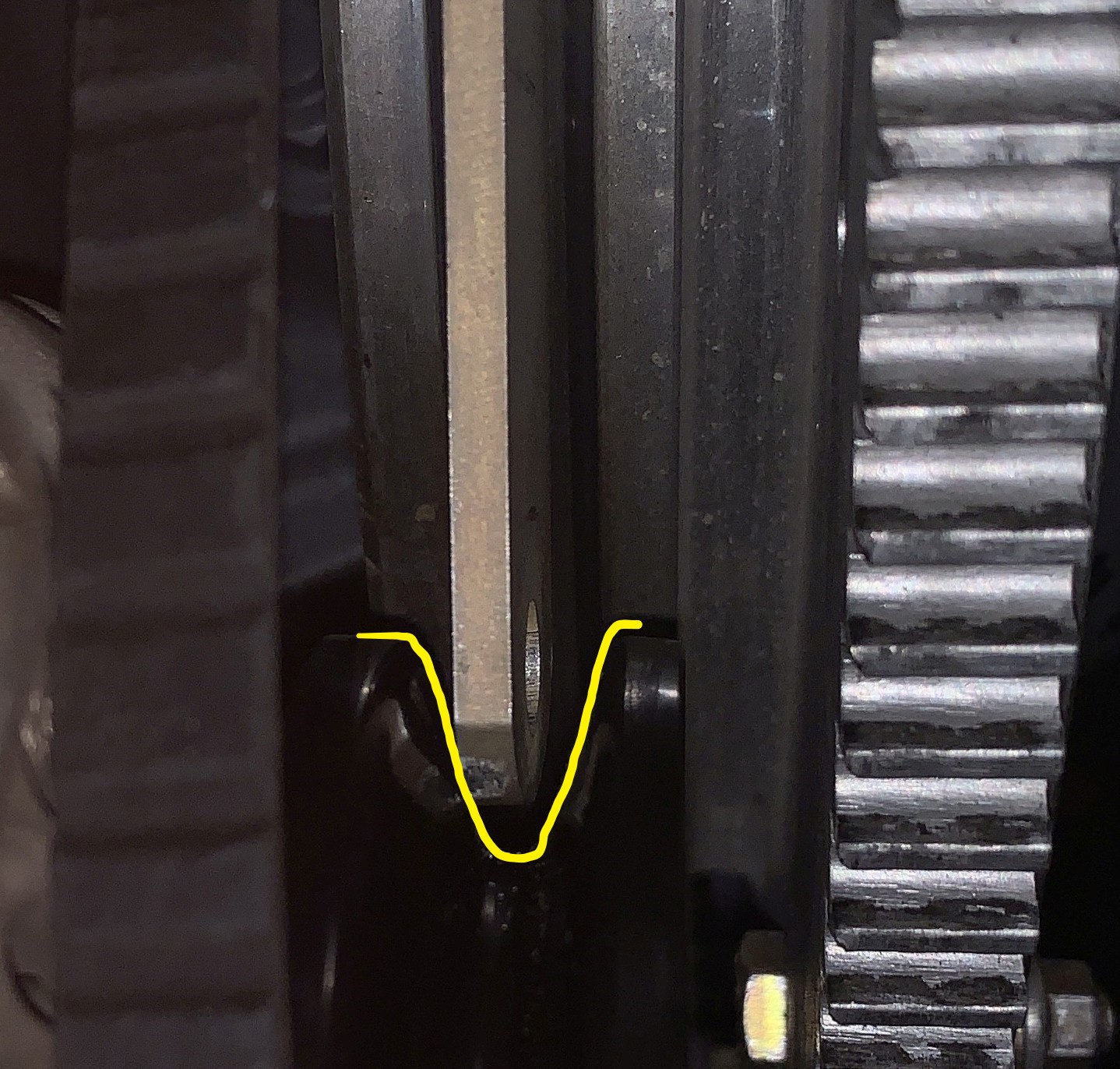 |
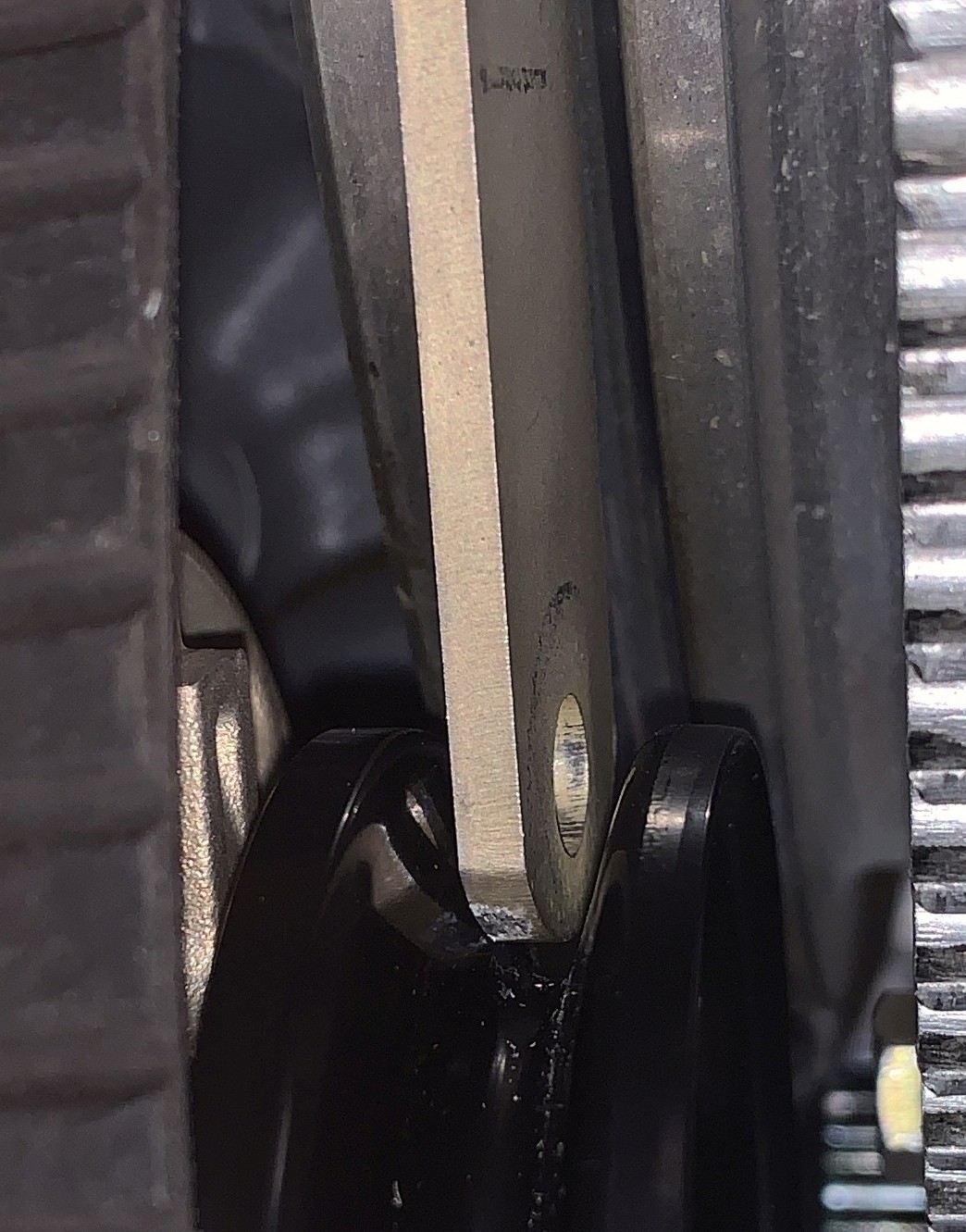
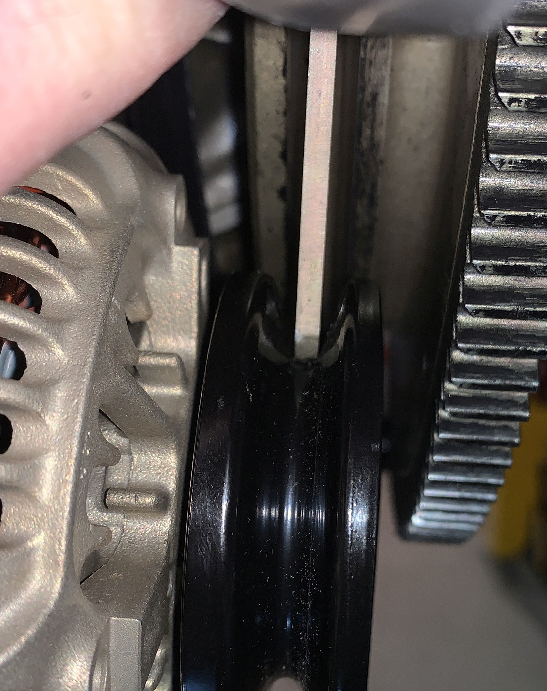
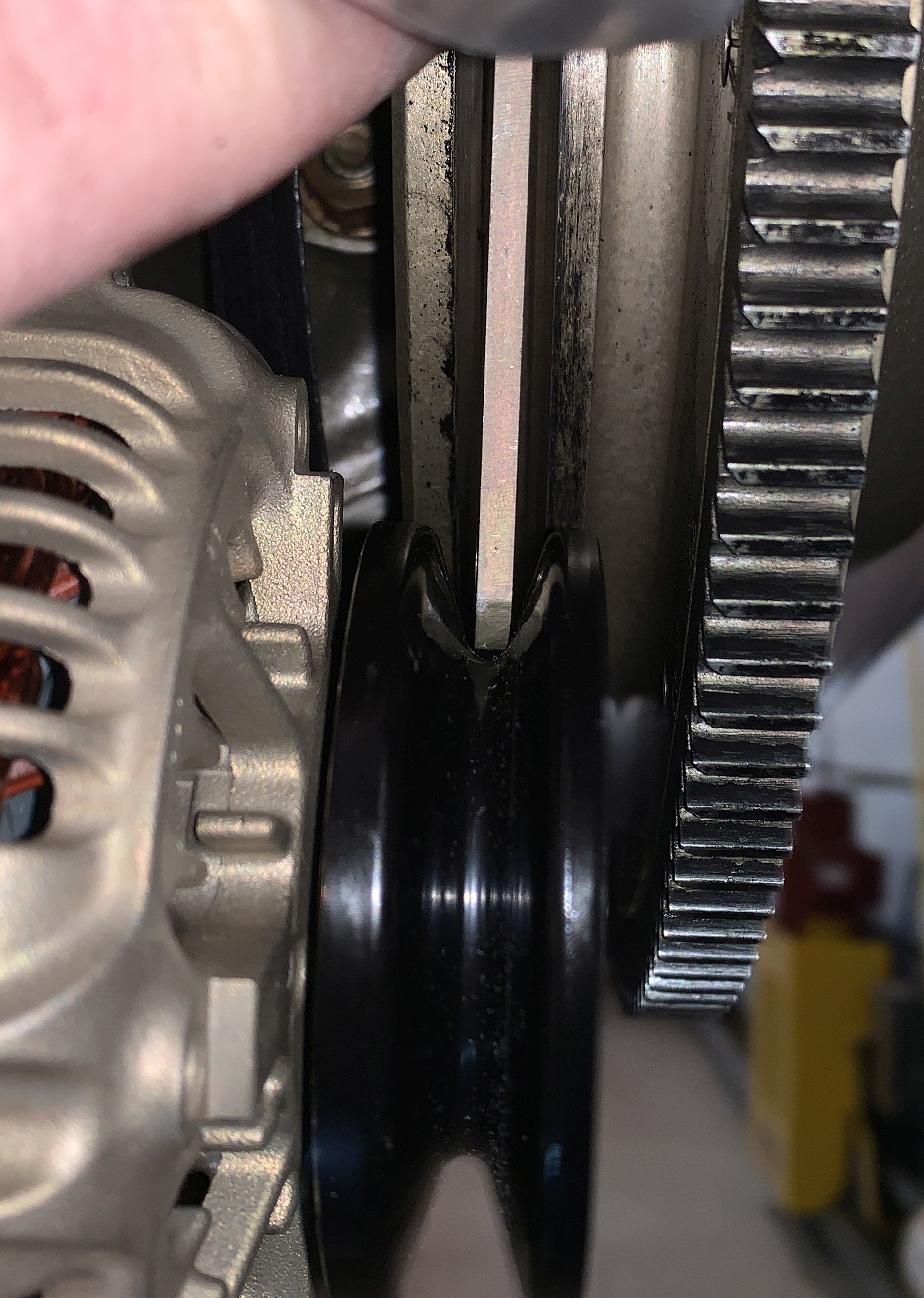
The pictures above and below show that if you slide the alternator adjuster bracket along the big pulley on the engine, and lift the alternator, you can use it as a guide to show where the groove will line up by seeing where the bracket hits the alternator pulley. It is very hard to get good pictures at the perfect angles because you have to make sure to align the camera lens with the pulleys to get the best view, but even though these aren't perfect, I've duplicated the picture and drawn in the pulley edge in yellow so you can see the misalignment better. Notice that the bracket hits the left side of the pulley about 1/4-1/3 of the way up from the bottom of the groove, rather than being centered. It was very hard to get an approximate measurement but I'm guessing something around .093"-.095" of a shift was what was required to center it. The 403-301-4 I think moves it .130" which makes the adjustment bar dig into the other pulley face. |
|
 |
 |
 |
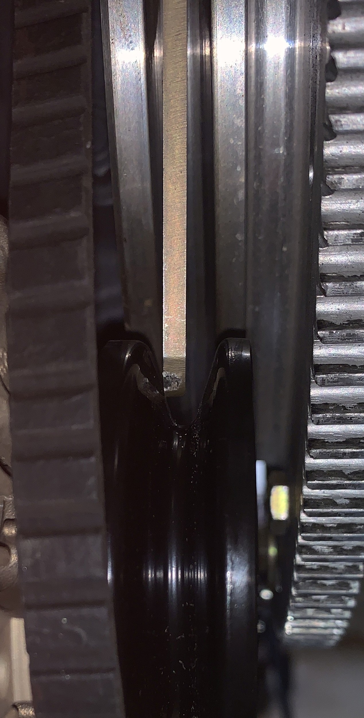
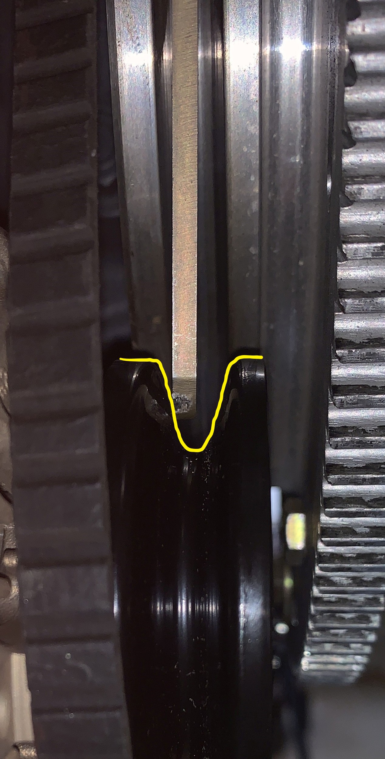
This is just another view
so you can see the edge of the bracket digging into the
pulley. |
 |
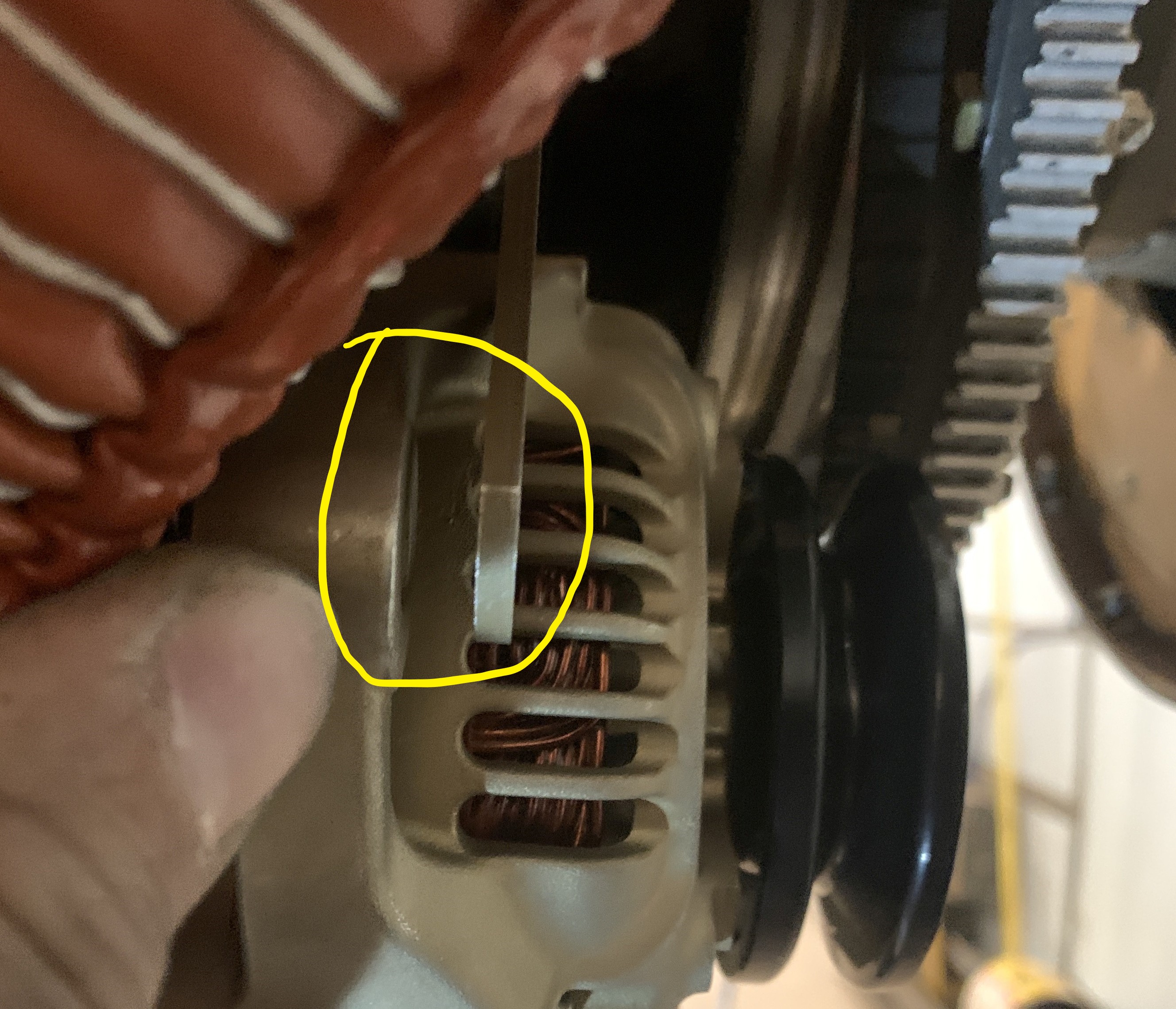
This is the oblonging of
the holes that I had to do, to get the alignment
proper. I had to elongate not only the round hole,
but the oval one as well. The engine bolts, by
default, center up in the middle of the oblong hole on the
original bracket, when both bolts are in. The extra
space in the oblong hole is not enough after making the
round hole also oblong, to fix the misalignment, so both
had to be filed. |
 |
 |
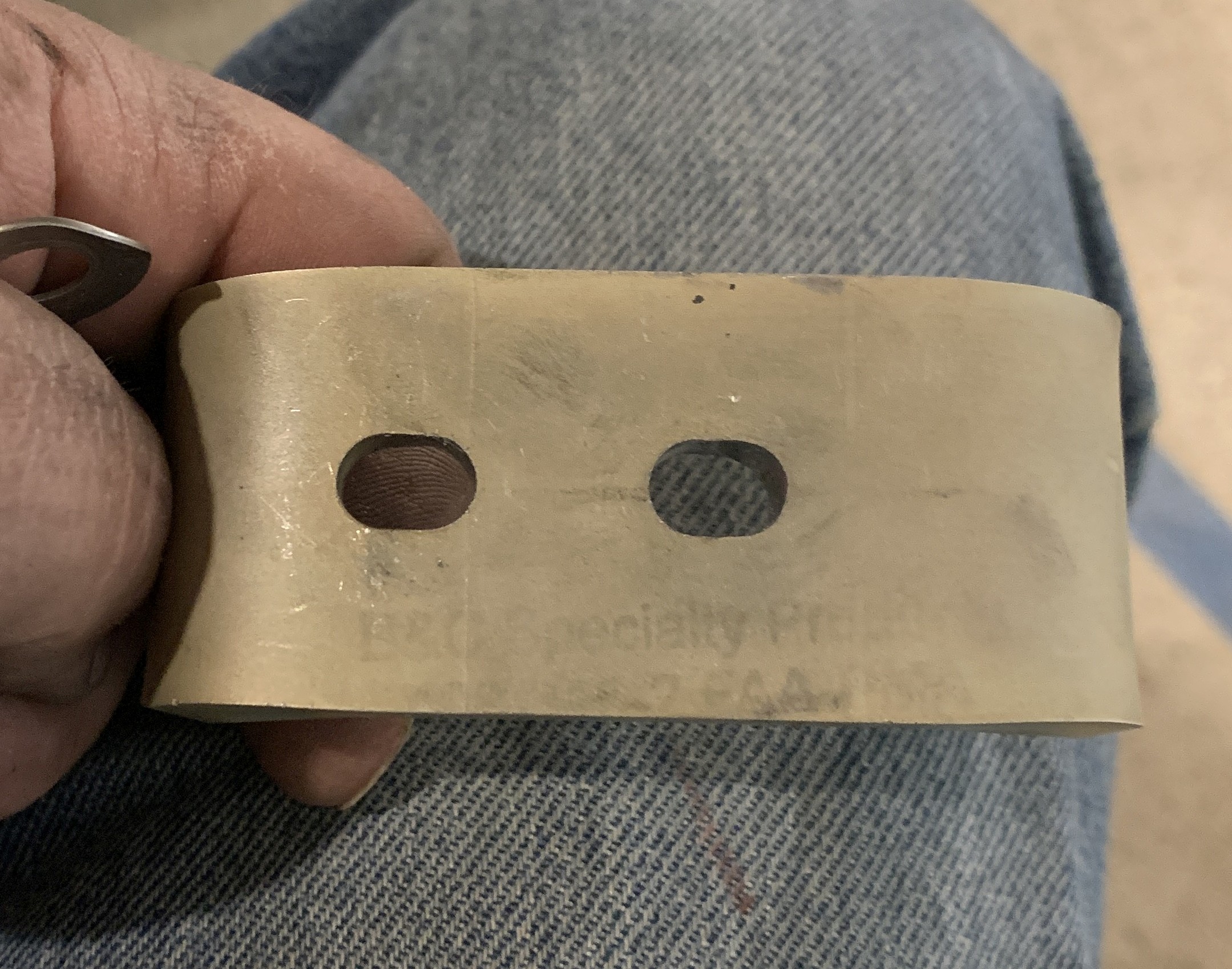
These 2 pictures above are a poor attempt to show the amount of shift. I originally filed the holes a little too far, so the bracket could be slid too far in the necessary direction, so I needed to make a mark so that I could have a reference when torquing up the bolts to know that I was moving it the right amount. In that process, I tried to take a couple of pictures of the mark so I could show how much the bracket needs to be moved. But, since there are no references such as the thickness of the marker line, it's not really useful for precision measurement, only for illustrating approximate shift necessary to align. |
|
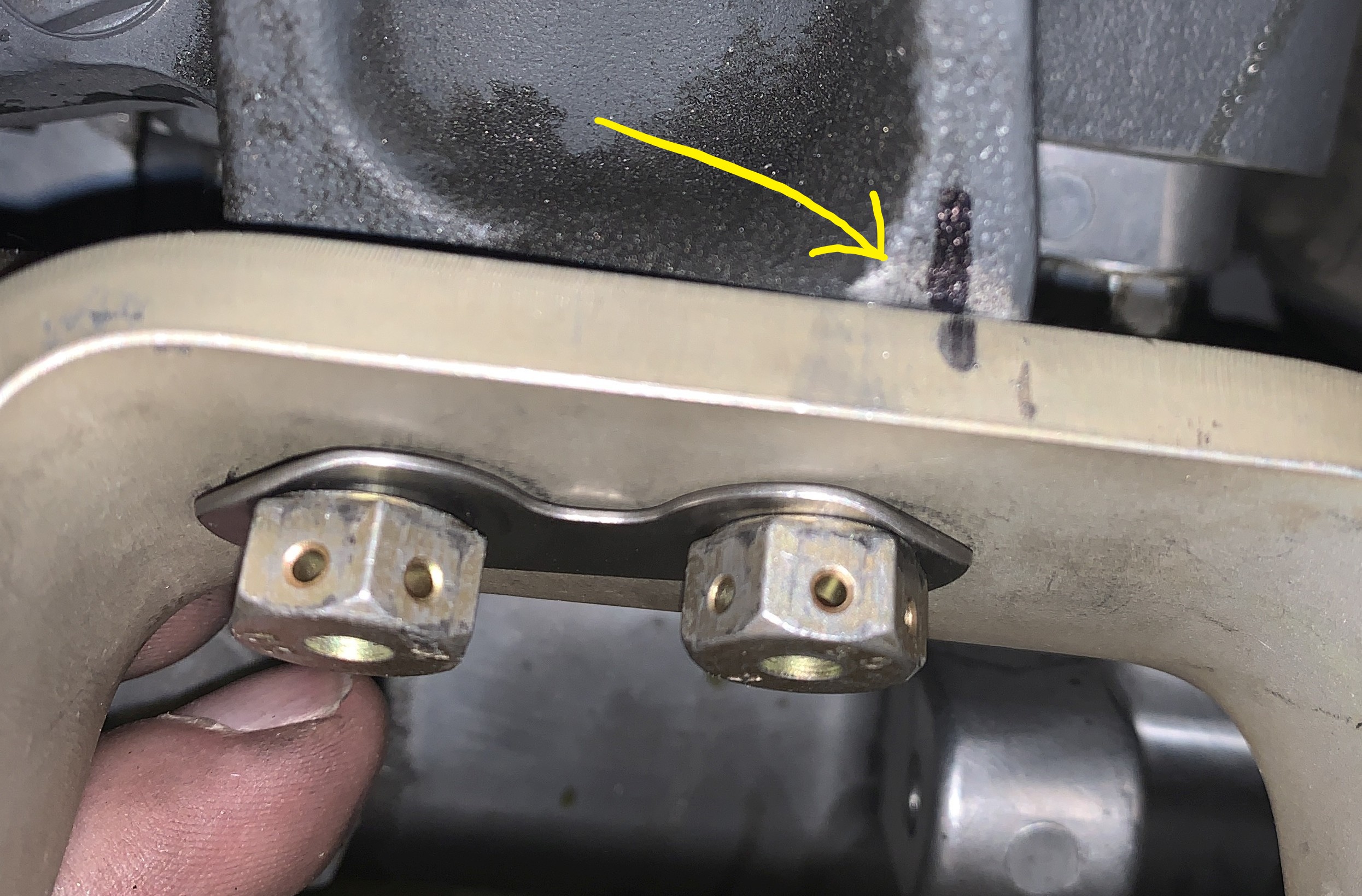
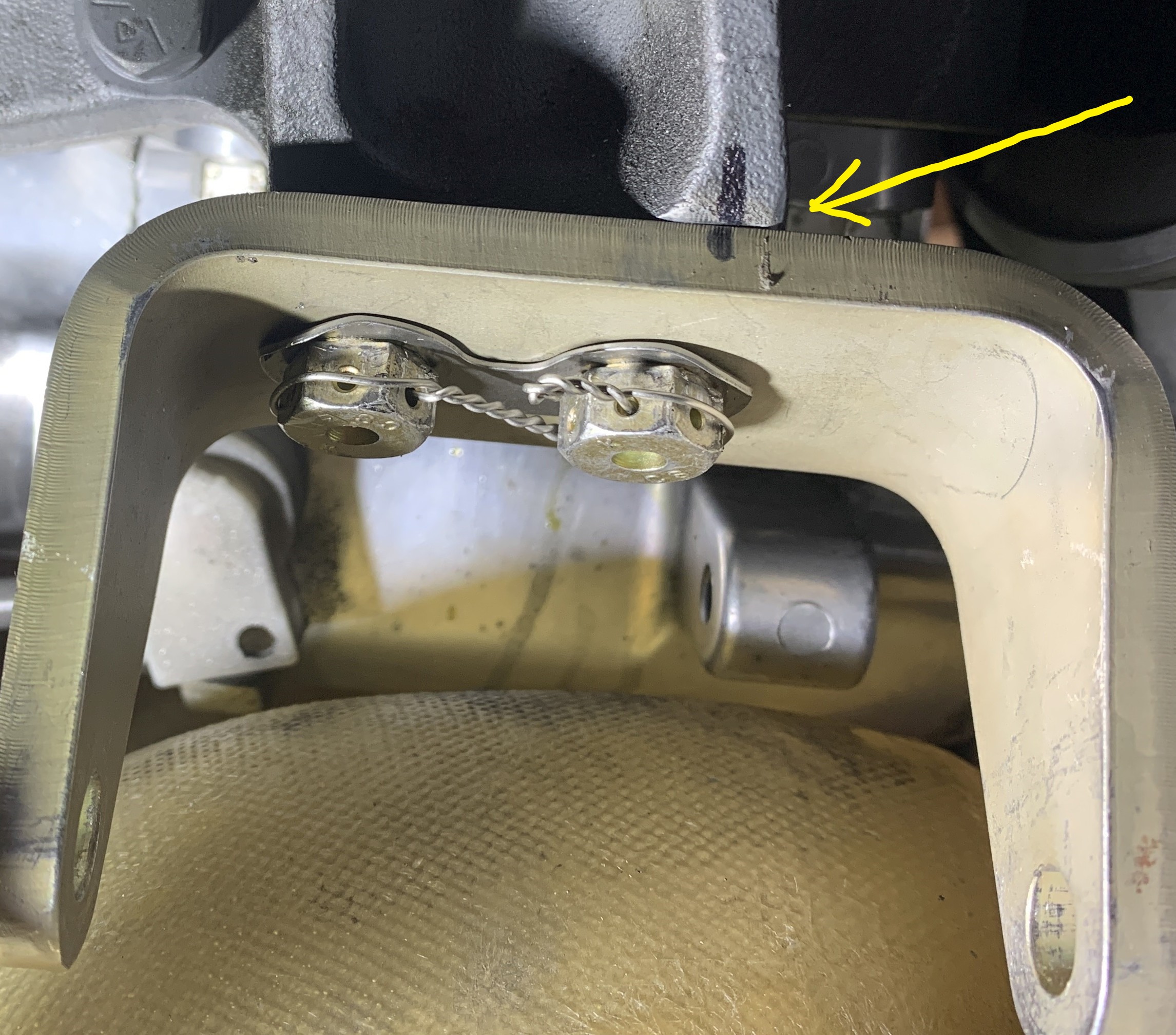
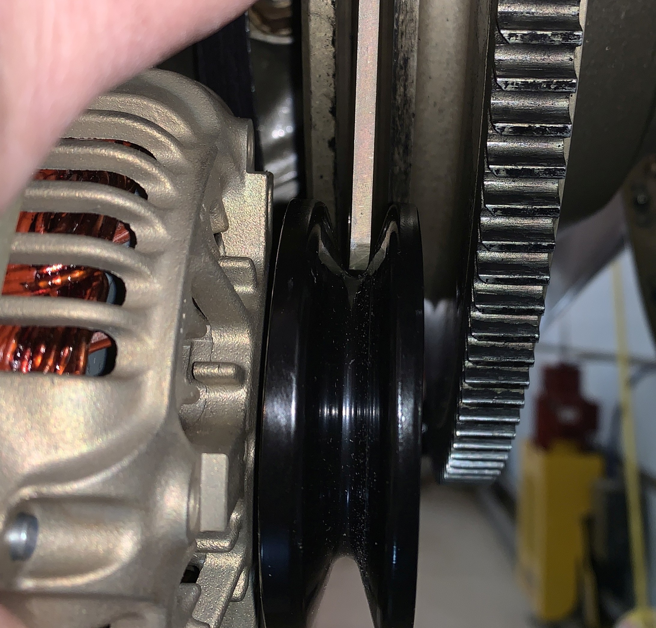
The following 3 pictures show the adjuster arm in position after correcting the misalignment. You can see that the arm fits nicely into the base of the V groove as well as can be expected. |
|
 |
|
 |
|
 |
|
One additional issue that I encountered is that the adjuster bracket should either be bent, such as Plane-Power does with their brackets (which are much thicker), or a second thick washer should be included. The gap between the adjustment arm and the alternator on both of my planes, IO-540 Narrow Deck and IO-390 Wide Deck, was about double the thickness of the thick washer that you supply with the alternator. I had to find washers with the same OD and drill them out for the same size center hole. Since I didn't have thick washers, I had to use 2 standard washers in additon to the thick one supplied with the alternator. This shows the gap and the stack. |
|
 |
 |