LOP (Lean of Peak) Injector Tuning
Added 8/22/2009Most people who have followed any of my flying will already know that I do a lot of X/C flying, and that I like to do it on as few dimes as possible. For me, Lean-of-peak leaning (LOP) is just the way I usually cruise. LOP has been proven over and over to have great benefits in the form of better cylinder cooling, lower cylinder pressures, cleaner operation, and for today's mindset, both cheaper (more efficient) operation, and more "green" operation (i.e. you waste less fuel and you pollute less with the lower consumption). If you search the web, especially some great articles by AvWeb writers, "Pelican's Perch" articles, AOPA, GAMI, and many more, you'll find that LOP operation isn't something new, but something that's been around a long time. But, what's new is that LOP is best done with some good equipment in the panel so you know exactly how your engine is set up and performing. When I started flying, the rentals I used didn't, for the most part, even HAVE EGT gauges in them. Then when I bought my first plane, I had ONE cylinders EGT/CHT probe on a gauge...which I then swapped out for a whole Electronics International UBG-16 system that did all 4 cylinder bar graphs for both EGT and CHT. That was MUCH better and I started paying more attention to how the engine was running. With the added information it was easier to diagnose the very common "fouled plug" problems. But, in todays world of instruments (mine were bought in 2005, so I guess it's really in "recent times"), things are much better yet. My Grand Rapids EIS 6000 feeds data on the engine into my Chelton screens which then graphically displays many engine paramenters, and the Chelton also includes a trend graph for EGT's and CHT's, and some great leaning tools for finding peak EGT. It also logs the data automatically on every flight, in 1 second intervals. This makes it possible to fly very precisely, and then go back and analyze the data and make corrections as needed.
The ability to make the corrections is where our world of Experimental airplanes really stands out. We have opportunities to have the best maintained, and best running airplanes in the skies. Why? Because when something breaks, we can fix it. If a part is inferior, we can improve it without getting an STC or filing a 337. If we do improve something, we ourselves can do the work and sign it off. And, if we see something dangerous, we can correct it and not worry that to be legal, we need to find an A&P and have them inspect and sign it off. We also have access to parts that not everybody has access to. For us Lycoming users, this means we can replace specific orfice sized injector restrictors with something other than the standard orfice. For most of us RV-10 builders, an injector will come with a standard .028 sized injector restrictor. For a certified plane, it would just stay that way, for the most part. We, however, have a great option...we can tune the injectors to provide the best flow for each cylinder, and Airflow Performance makes that possible by offering a variety of injector restrictors that are stepped in sizes that are of .0005 variation. So we can have .028, .0275, .027, .0265, .0260, or whatever we need to make our engine run the best it possibly can. No two cylinders will have the exact airflow distribution, which means that any two cylinders that have the same fuel flow may not react exactly the same when leaned. By balancing the flows properly, we can get the best air/fuel mixture to provide the peak EGT to happen at nearly the same time for all cylinders...which leads to a better running, smoother engine...one that also has a good chance of operating LOP well. Just for your reference, what you're shooting for is that your cylinders all peak within .2 gph of eachother. What does this mean?? Well, as you lean from, say, 14gph to a LOP fuel flow of maybe 10gph, each cylinder will peak out when it gets the fuel flow that provides the hottest burn. One cylinder may peak at 11.5 gph, and another may peak at 11.9 gph. This would be a spread of .4 gph if you were talking about a 2 cylinder engine. For our RV-10's, with 6 cylinders, you have to try to get all SIX cylinders to peak within .2 gph of eachother...so less is better, and more isn't necessarily horrible, but if you shoot for .2 gph or so, you'll be doing really well.
Before I get into what I did, I will make note of what I have for a system. I have a Lightspeed Plasma III ignition system on my top plugs (Right side operation), and the top plugs are auto type plugs. I have a Slick mag, 6350 series, on the Left side. My Lightspeed system was installed by Aero Sport Power, in Canada...one of the many great engine builders for RV-10's, and one that has an awesome reputation in Minnesota/Wisconsin with the RV'ers around here. My mag was installed by them too, but I did have to do the mag overhaul to meet the slick SB...so I timed it standard as it was delivered to me. My Lightspeed mag drop is about 10 RPM, and my Slick mag drop is probably about 50 RPM. I say probably because I don't have a readout that reads when the lightspeed is disabled, but by ear you can tell that it's nowhere near 100 RPM. My fuel system is the Precision Airmotive SilverHawk EX system, which many people call a standard "Bendix" system. I tell you this because although some RV'ers use Airflow Performance injection and then go through the same injector balancing process, it is not required for you to be able to use these restrictors...the injectors themselves are the same injectors.
One other thing you may note is that I'm finally writing this at 540+ hours of engine operation. Why? Well, I finally had the ambition to improve things, I guess. When Bart at Aerosport builds engines, he flow matches the injectors on a bench and tries to make them very good. He balances the engine well, too. So he takes great care to make sure it's going to run real well...and mine did. But, with variations over time such as my new cylinders, and everything else, there is really only one way to make things close to perfect and that's gather real flight data and use that as your tool. My engine did run real well in LOP operation. It runs smoother LOP than it does ROP, in fact. I could always lean to at least maybe -90F LOP EGT and the power just dies off...the engine doesn't really even run rough...it just fades in power. So with that as a normal operation, there really wasn't any huge motivation to spend time and money and flights to improve the LOP operation. But, being a perfectionist, it was always on my "To-Do-List" to get things tuned in even better. As it turns out, it was silly that I waited this long because the data is so bloody easy to get, I could have done it on any old x/c flights and just improved it as I went.
Oh, and one more thing to point out... With the Chelton downloading my data every 1 second, I had a great log of data, but the logfiles aren't organized very easily to read. Here enters another great part of the tools I used...EGView, by EGtrends. EGView is a software program that can read a few different system's engine logs, and provides graphical and table based analysis of your logs. You can graph cooling against airspeed, airspeed against fuel flow, or basically take most any input from your EIS and graph and compare. It also contains a "GAMI Lean" test, that is designed just to load your curve, zoon in on the actual leaning curve, and it will analyze the curve and tell you which cylinder peaking order you have, and how far apart your fuel flows are. I found it to be a great tool. I didn't use the "GAMI" test religiously though....because I wanted to interpolate the data myself. Automatic systems will generally look for where the EGT's start to drop, but depending on how long your cylinder plateaus in temp, the fuel flow may vary a bit without the temps changing all that much. So I myself tried to look for the center of the peak of the curves, and I looked at the fuel flows over the whole peak (which helps get rid of variations due to fuel flow bumping up or down by .1 or .2 gph). It was very easy to do, since EGView gives the table based data too. I should warn you...if you ask Airflow Performance how to do it, they have a great method, but it takes a lot more time and effort in flight to get things recorded. You lean in .1 GPH reductions and write down each EGT at each fuel flow, until you're all the way done leaning. By using EGView, and interpolating a little, I was able to do it without doing any manual recording in flight...just go fly, and come back and look at the data. By providing them the exact fuel flow that each cylinder peaked at, they were able to suggest which injector restrictor size to use. It was a very quick and easy process. So with that lengthy intro, lets get on to looking at the data!
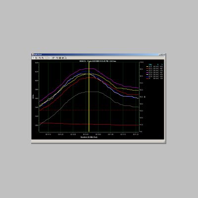
| Starting from Scratch .028 restrictors all the way around |
|
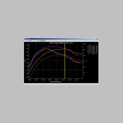 5 @ 11.0 2 @ 11.0 6 @ 10.7 4 @ 10.4 3 @ 10.2 1 @ 10.1 .9 spread |
 5 @ 11.0 6 @ 10.8 2 @ 10.8 4 @ 10.4 3 @ 10.2 1 @ 10.1 .9 spread |
| Looking
at these first 2 leaning charts that I did on my flight this year on
the way home from OSH 2009, you can see that the curves look pretty
similar. They aren't perfect, however. My own analysis of the
first 7/31/09 graphs is posted above...and you can see that even though
my engine ran fine LOP for a long long time, I was looking at a pretty
good spread in fuel flows at the various EGT peaks. NOTE: You really
should lean at least 2 times for each session, and let things stabilize
well, because there are so many factors...some of them in just HOW you
analyze the data, that can make readings go from .2 to 1.2 variation
just in how you interpret it. The curve itself though doesn't lie...if
you are very close, your curves will rise and fall in unison. So by
looking at the curves you know how well you're doing. My .9 spread
number therefore may be VERY subject to interpretation, and it could be
much more or much less...and in fact it was, depending on what methods
I used. |
|
|
|
|
|
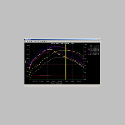
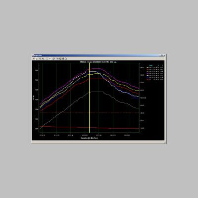
Second Attempt
.0270 restrictors in cylinders #1 and #3,
and .0275 restrictor in cylinder #4
|
|
 3 @ 11.2 5 @ 11.0 2 @ 11.0 6 @ 10.7 4 @ 10.6 1 @ 10.5 .7 Peak Spread |
 3 @ 10.6 5 @ 10.6 6 @ 10.6 2 @ 10.6 4 @ 10.5 1 @ 10.5 .2 Peak Spread |
| After
giving the above 2 tables (the text, not the graph) to Kyle at Airflow
Performance, he suggested using .0270 restrictors in #1 and #3 to pull
those curves back quite a bit, and a .0275 in #4 to adjust that one
back a little less aggressively. Restrictors cost $25 each and are
non-returnable, so it wasn't a very costly task in comparison to how
much money you can save by running LOP. (More on that below) Airflow Performance is
available at 864-576-4512. You can see that the curves definitely
improved a bit. Some of you may be wondering about that crazy #3
though...why is it always so low. Well, first of all, you don't really
CARE what temps you are at for leaning. The temperature itself is
unimportant...but WHERE it peaks is what matters. So, I don't really
have a lot of worry as to why it's low. But, it could be low because my
probe is bad. By all means, that cylinder is getting the same EGT peak
curve in general as the others, so it isn't likely that it's an
induction leak or anything like that. A probe is probably the most
likely thing, in fact. Later on I'll try to get around to swapping
probes or replacing it and see what happens then. Looking at the data
though I came up with those 2 tables of figures, and as you can see,
depending on how the curve looked and how I analyzed it, I could call
it either a .7 gph spread or a .2 gph spread. I showed the numbers to
Kyle again and he suggested I fly and do more testing before I go
forward because I might be doing pretty darn good as it is. So I
did....I flew 3000nm on a trip and verified that on a couple other
flights I had very similar curves...with #4 and #1 peaking later than
the others...being the "odd two out". So, I tried my own hand at the
guessing game and ordered up a .0265 restrictor...with the plan being
to move the .0270 from #1 into the #4 cylinder...reducing it from .0275
to .0270. Then, put the new .0265 in cylinder #1. So both cylinders
would be reduced by .0005. That should make them leaner and bring the
point of leaning back a little further. One other thing that Kyle
warned me about is that when you change one injector, such as by
reducing it, you will affect the others slightly too. The fuel flow
volume may remain the same, so by restricting one, the increased
pressure may make others flow more. |
|
|
|
|
|
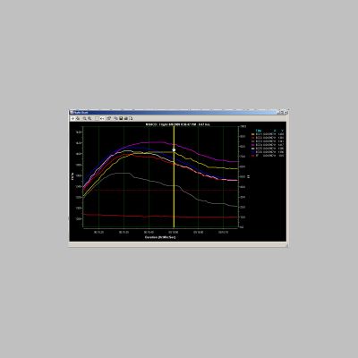
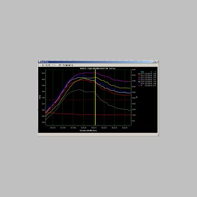
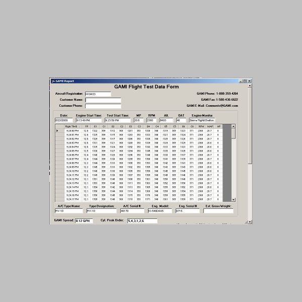
Third and probably Final Attempt
.0265 restrictor in #1 and .0270
restrictors in cylinders #3 and #4
|
|
 5 @ 10.8 6 @ 10.8 4 @ 10.8 3 @ 10.8 2 @ 10.8 1 @ 10.8 0.0 spread |
 5 @ 10.8 6 @ 10.8 4 @ 10.8 1 @ 10.7 3 @ 10.8 2 @ 10.8 .1 spread |
| So there
you have my 3rd attempt. You can clearly see how the curves have pulled
back so they are all very very close in when exactly they peak. The
data gathering I did is again a little open to interpretation but in
general it really looks like I've obtained .2 gph or better on all
cylinders when looking at the raw data. Below I've attached the table
form of the GAMI report that EGView generated, and you can see it calls
the spread .12 GPH. Using the tool the data can vary quite a bit based
on how you set up the curve to be analyzed, but as I said above, the
curves don't lie...so if it looks really close, it is really close. |
|
 |
|
So after going through the whole process, like I said, I think it's silly that I waited. It only cost me $100 in injector restrictors to get it all done right. I now own the old ones too, so if I ever want to experiment, they are all labeled in baggies and I can move them around as necessary. So is $100 worth it? Well, if it helps you run LOP I say it is. Why?? Check this math out a bit. By running LOP, I ALWAYS save at least 3 gph over running ROP. I typically lose about 6-8kts in cruise speed, and on a 160nm leg that only adds up to a couple minutes. I've flown along running LOP and thought I should run ROP to get there quicker, and after raising fuel flow 3-4gph, I've saved maybe 2-4 minutes of flight time. Over an hour, 3-4 gph is worth $12 - $16 in fuel at least. On my last trip out West, we had to fly a 3.75 hour leg. Running ROP we may have had to plan a fuel stop to be conservatively safe on range. Running LOP we saved nearly $50 in fuel on that one leg alone, and had enough fuel for nearly 2 hours of extra range. So if you get into the habit of running LOP on long flights, you can save HUNDREDS of dollars. On my last trip which I'll be writing up soon, we flew over 3,000nm, and probably saved in excess of $300-400 in fuel by running LOP just on that one trip. We also fly many legs of trips where we push into the 4.5 or even over 5 hour legs, allowing us to save time on the overall flight, and not spend the extra fuel to land, taxi to the pump, fill up, and climb out all over again. So, if you fly LOP on every flight, you will probably even BEAT the total in-flight times of a ROP flier, because you're not stopping as often, and you certainly will be spending less money on fuel, and be able to land with more fuel reserve. It's one of the few "win, win, win" situations you can have in flying. In fact, since Fuel Injected engines run LOP far easier than carbureted engines, you can EASILY pay for the increased cost of fuel injection in a very short time, just by flying LOP!
Flying LOP Tips: In all the reading I've done, what I've found is that most commonly it's recommended to be under 75% or even under 65% power when running LOP. There are some newer engines in planes like the new Cirrus's that run LOP even in climb, but they seem to be monitored or controlled in order to do that. For our purposes, the safe way to run LOP is to do it under those percentages of power. This generally means running LOP at higher alittudes, where the engine can't MAKE more than that amount of power. Typically this means that I don't start running LOP often unless I'm flying at 7,000 msl or higher...and I recently found that it's unlikely that you'll have luck running LOP when up above 15,500...I found that out in real life use. By not running LOP at lower altitudes, you're helping provide protection against that nasty range between 100F ROP and peak EGT, and the cylinder pressures that can be generated at lower altitudes. This does NOT mean that you can't run LOP at lower altitudes, but it does mean that you want to run at lower POWER levels when running LOP. So, I generally set up the plane for x/c altitudes of 7,500-10,500 and then run it LOP. My manifold pressures are typically under 22" when running LOP. When I want to descend and save fuel, I just keep pulling back the MP on descent, since I have good airspeed from descending anyway. Doing this, I can have fuel flows of even 5-7 gph or so when coming down. My MP might only be 14" or whatever, so I'm trying to keep power levels under 75% for sure. You can run LOP even at low altitudes if you wish, to save money while tooling around with your sorry buddies who are forced to fly cessnas and other meager aircraft. Just keep that percent of power low and run LOP like usual. Doing this you can easily cruise around on 7-8 gph at 125-135 kts at 3,000' or whatever, and save tons of money while sightseeing.
A quick note on leaning during climb.
As many of you know, when you takeoff at altitude, especially over 5,000' of altitude, you will need to lean to get the proper takeoff power. A trick I learned a while back is that during climb, all the way up, you can lean to about 1225 degrees EGT, and if you maintain that temp your engine should be roughly leaned appropriately for climb. If you go full rich and try to climb to 8,000-10,000', your EGT's will be too low and you won't be making much power. In addition, I've worked with one person who had a Carbon Monoxide issue, and when I asked what the EGT's were, they sounded very low. By leaning out the engine a bit and raising the EGT's, the CO problem went away. So leaning is very important during cruise and climb.
Final note on restrictor removal: When you go to swap restrictors, it only takes about 2 minutes per cylinder if the cowl is off. The restrictors are slid into the injector body, so all you need to remove is the nut and move the stainless fuel line over. The restrictor lifts right out. You most likely DO NOT want to remove the injector body. If you do, you need to clock the body properly on re-install so the vent hole under the screen is at the low point, and you will need to properly torque the injector. If you do this, you DO NOT use any lube or anti-seize on the injector body. So, keep it simple...just pull the nut, move the line, and pull the restrictor out. It takes almost no time and accomplishes the job. Regarding the restrictors, they are very small conical shaped items with an orfice in them. Don't overtorque the nut on top of them or you can damage them. The stock restrictors are stainless steel. If yours are the standard .028 size, they will have ONE band around the center. You need to use the restrictors sized for your injector bodies. .028 is probably standard for all of us in most cases, but to be sure, before you order some, pull one of yours and look for that one band on the center. The ones provided by Airflow performance are Brass. These aren't legal to use on certified planes. They are also stamped with the size of the restrictor.
Now, tune your injectors, fly LOP, and save tons of money!
EXCEPTIONS!
Although I thought I had a good handle on running LOP, there is one exception that I've run across. I've found 2 people with IO-540's with identical ignition setups as me, but they were running Airflow performance injection systems and 10:1 pistons. Neither of those guys have been able to get the engines to run LOP. In fact, on my last trip I flew one of those planes and tried for myself and it stumbled even before reaching peak EGT. I've started doing some investigation into the situation on the one plane, because we'd REALLY like to get him running LOP. The injector balance is great...at least as good as mine is now, so it shouldn't be the fuel system. The ignition is the same as mine so that is probably ok too. But, high compression changes things like optimum timing curves, and timing differences between the mag and EI can cause various changes too. Spark plug heat ranges may change with compression ratings, too. One suggestion given to me by Airflow Performance AND by Lightspeed Ignition, is to start by replacing ALL of the restrictors with .0260 sized restrictors, to increase fuel backpressure in the system...providing better atomization. This step is going to be our first step. Klaus from Lightspeed says that also required is to use an actual timing LIGHT on the ignition systems and verify the timing of the 2 systems. Supposedly there are timing marks on the back side of the ring gear that will line up with the top engine case seam, and you can time the systems and read the reading from standing behind the prop next to the cowl. On the lightspeed where there is a waste spark, you will get firing on 2 cylinders from each coil, with the waste spark. He says to use a REGULAR timing light, not one with advance. NOTE: Timing the engine using a timing light can be very dangerous due to you doing the work near a moving prop. Stay clear and be ultra careful if you do this. I've heard from one A&P who says that static timing of a mag can be very accurate and he doesn't recommend strobe timing. So opinions out there vary. Whatever you do, do it safely and keep your distance from those blades! Hopefully, with luck, we will find that using smaller restrictors and by doing some timing tweaking of the mag or maybe even EI, we can get the engine running LOP just fine. Klaus from Lightspeed says that the compression shouldn't prevent it from working, but I find it interesting that both people that I know that simply couldn't get it to work, were running high compression engines. It's because of this and long-term engine life that I'd recommend that if you are planning to do lots of x/c flying and want to run LOP, you may want to consider this information in your choice of engine compression and how you outfit it. I'll report more here as I learn more about getting that engine to run LOP.
Additional Information
Here are a couple of documents people sent me to share.
GAMI LOP info
How to Lean for Takeoff and Climb at Any Altitude - Advanced Pilot Seminar