Improving Cylinder Cooling Through Baffle and Cylinder Work
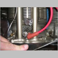
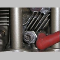
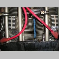
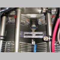
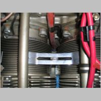
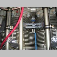
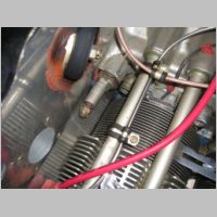
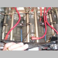
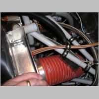
Updated 1/9/2006 - Updated 3/24/2007 with linkSurprisingly you'll find on most cylinders, there are some improvements to airflow that can and should be done. These photos below will show the area as best I can. Vic was the one who pointed this out to me during the LOE Fly-In, as his CHT's were running lower than mine were by quite a bit...at least 25-40 degrees it seemed. If you notice between the valve pushrod tubes, there is a small area of fins just outside of the spark plug holes. (Note that the sparkplugs are removed in most of these photos, and the spark plug hole is covered with aluminum tape. The plugs are just sitting there.) If you look closely between these fins, you'll find aluminum "flashing"....some rough ridges of aluminum that stick out into the slots where the 2 cylinder halves meet, where the casting came together. You'll also see some around the fins all around the cylinders anywhere the halves came together, but the stuff between these valve pushrods is the most critical. The top of the head is where most of the heat will be concentrated, and any restriction to airflow in this area will prevent good cooling.
To fix this, I bought a file and cleaned out the flashing, the details of which I've posted in the TIPS section HERE.
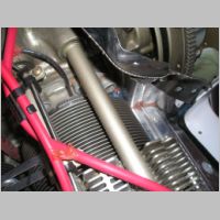
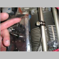
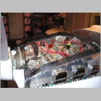
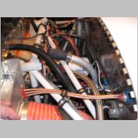
Additionally, I tried to improve my baffling a bit, although it was already pretty good. I added a bead of RTV between the cylinder heads, the purpose of which is to restrict the air from flowing between the heads...it is now forced to pass by the cylinder fins. Also, if you look deep down in between the cylinders, you'll see I used some blue RTV to seal any visible holes in the inter-cylinder baffle to engine case area. This will keep the airflow from leaking out in useless areas. Other areas not to miss are around the grommet for your fuel line going up to the flow divider, and deep down in under your vernatherm, and around the front of the cowl area. I also stuck some right in front of the cylinder fins on the #1 and #2 cylinders.
Speaking of in front of the #1 and #2 cylinders....
From the sounds of it, most of us builders who've been flying a while and have invested some time in improved cooling, have had to deal with these #1 and #2 front cylinder baffle dams. When I first started flying and noticed high temps on #1 and #2, I trimmed 1/4"-3/8" off the tops of these dams. It gave a definite improvement. On further flights in warmer weather, I ended up trimming them again, so now they were down 3/8-1/2". It was still getting better. Then, I trimmed them one more time and still saw improvements. So I started to actually think harder about this and look at the cylinders closely after I filed the flashing out, and looked at the shape of the cylinder heads. Knowing that the tops of the head get the hottest, you'ld want to give them good cooling, right? Well, this baffle as it was orignally made, blocks all of the air flowing front to back over the cylinder fins, and I don't for a minute believe that the air entering the cowl is ready to do a 90 degree downward turn behind the baffle and go straight down. So, I got to thinking that I should try to make the baffle fit the curve of the cylinder fins a bit. This is the result, and it was in place in this manner when I got the temperature results below. Now I'm happy with the results. It should be noted that some other builders have removed these completely, which may be better, or worse, but I haven't trimmed them any further than this, as it would be hard to re-rivet them on if I drilled them off.
|
|
Sealing up your aluminum baffling
On the side of your baffling, you'll also want to fill some between the aluminum panel sections to prevent leaks if they bow or flex, and you should also shoot some RTV in the gap between the baffle gaskets and the aluminum baffling, in case air leaks under the seal. Once you get all of this done, your baffling will be in much better shape.
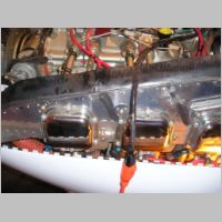
A couple of the last pictures in this set are just there for my records for looking at engine areas.
|
|
|
|
|
|
|
|
|
|
|
|
|
|
|
Cowling Work
Lately I
was watching a VansAirforce RV-List thread regarding the baffle sealing around the air
ramps that are glassed into the cowling top. The issue is, at
least on the smaller RV's, if you have some baffle areas not sealed
around the inner edge of the ramp, air can leak out form the HIGH
pressure side (above the engine) and leak THROUGH the ramp, and exit to
the LOW pressure side of the baffled area on the outer end of the
ramps. This is 100% wasted cooling air, and for some of those
people, it was a significant leak. I thought my baffling was
pretty good after the steps taken above, but I hadn't yet checked along
the top cowl by the air
ramps.
What I found was that I had sealed the outer ends of the ramps fairly
well, but not perfectly, and the inner ends were wide open.
On
the Right side of the engine, the baffling seals well though, so I'd
have no leakage at all. On the Left side however, the prop
governor complicates things greatly! The rubber baffle
gasketing
goes nicely over the top of the prop governor, but you have to cut a
hole in the ramp for the governor to fit, and what I found was on the
back side of the governor area, it was open to allow air up by the
governor and into the area above the ramp. Then it could leak
out
on the small leak on the outer end of the ramp, but the WORST part was
there was no block for the air on the INNER end of the ramp.
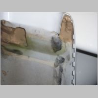
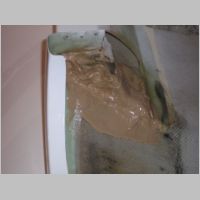
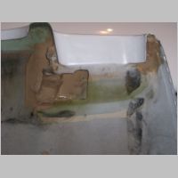
Below you will find some of my most embarassing epoxy work ever, but
I'm not done cleaning it up yet in the photos. I used some
spray-in expanding foam to fill some of the area under the ramps, and
then epoxied the areas on the outer forward noses of the front corners
of the cowl. My seal was good before, but I just wanted to
ensure
no ramp-leaking-air could come out, and wanted it built up a bit more
for the baffle seal to fit against.
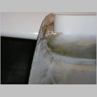
So I filled in some spray foam as the base of the ramp (which is why it
looks so rough), and then I put a couple layers of glass over it, along
with fairing filler. This sort of completes the ramp on the
back
side of the governor. BUT, there's a problem. (Try
this
glass area with duct tape first!) When you build the ramp,
it
runs RIGHT over the prop governor area, and the forward top corner of
the governor will hit the ramp if it's laid smooth with the rest of the
ramp. So this ramp area is actually concaved a bit, to fit
the
corner of the governor. If you put duct tape across, like I
did,
you'll find an indentation where the governor goes. You can
then
build this ramp accordingly. What the photos don't show, is
that
after I got done with this part of the job, I ground it down smooth
with a dremel tool, and then had to eat down into the spray foam a bit
more to provide more clearance for the governor....then re-epoxy that
area a bit more to cover the foam.
So the effect is that I now have a much tighter seal behind the
governor. It may still be leaking some, but by putting some
RTV
on the cowl top, and covering it with waxed paper and placing the cowl
on, it should construct a nice RTV seal on the cowl. I'll be
doing that part later.
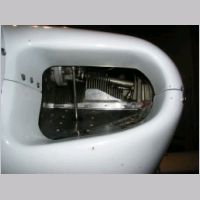
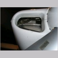
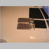
About the photo with the Louvers.... I bought these louvers
because some people used them to drop their CHT's down by about 25
degrees. After flying with my filed cylinders, the improved
baffle and engine sealing, and this cowl job, I'm now thinking I will
not bother installing the louvers. I'm actually worried that
if I
do that, I may get too much cooling.
So on to some flight testing...
Cowling Work
Lately I was watching a VansAirforce RV-List thread regarding the baffle sealing around the air ramps that are glassed into the cowling top. The issue is, at least on the smaller RV's, if you have some baffle areas not sealed around the inner edge of the ramp, air can leak out form the HIGH pressure side (above the engine) and leak THROUGH the ramp, and exit to the LOW pressure side of the baffled area on the outer end of the ramps. This is 100% wasted cooling air, and for some of those people, it was a significant leak. I thought my baffling was pretty good after the steps taken above, but I hadn't yet checked along the top cowl by the air ramps.What I found was that I had sealed the outer ends of the ramps fairly well, but not perfectly, and the inner ends were wide open. On the Right side of the engine, the baffling seals well though, so I'd have no leakage at all. On the Left side however, the prop governor complicates things greatly! The rubber baffle gasketing goes nicely over the top of the prop governor, but you have to cut a hole in the ramp for the governor to fit, and what I found was on the back side of the governor area, it was open to allow air up by the governor and into the area above the ramp. Then it could leak out on the small leak on the outer end of the ramp, but the WORST part was there was no block for the air on the INNER end of the ramp.
Below you will find some of my most embarassing epoxy work ever, but I'm not done cleaning it up yet in the photos. I used some spray-in expanding foam to fill some of the area under the ramps, and then epoxied the areas on the outer forward noses of the front corners of the cowl. My seal was good before, but I just wanted to ensure no ramp-leaking-air could come out, and wanted it built up a bit more for the baffle seal to fit against.
So I filled in some spray foam as the base of the ramp (which is why it looks so rough), and then I put a couple layers of glass over it, along with fairing filler. This sort of completes the ramp on the back side of the governor. BUT, there's a problem. (Try this glass area with duct tape first!) When you build the ramp, it runs RIGHT over the prop governor area, and the forward top corner of the governor will hit the ramp if it's laid smooth with the rest of the ramp. So this ramp area is actually concaved a bit, to fit the corner of the governor. If you put duct tape across, like I did, you'll find an indentation where the governor goes. You can then build this ramp accordingly. What the photos don't show, is that after I got done with this part of the job, I ground it down smooth with a dremel tool, and then had to eat down into the spray foam a bit more to provide more clearance for the governor....then re-epoxy that area a bit more to cover the foam.
So the effect is that I now have a much tighter seal behind the governor. It may still be leaking some, but by putting some RTV on the cowl top, and covering it with waxed paper and placing the cowl on, it should construct a nice RTV seal on the cowl. I'll be doing that part later.
About the photo with the Louvers.... I bought these louvers because some people used them to drop their CHT's down by about 25 degrees. After flying with my filed cylinders, the improved baffle and engine sealing, and this cowl job, I'm now thinking I will not bother installing the louvers. I'm actually worried that if I do that, I may get too much cooling.
So on to some flight testing...
|
|
|
|
|
|
|
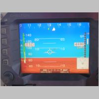
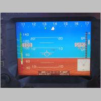
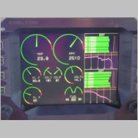
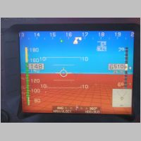
Climb Phase
This set
of photos was taken
during a normal climb to 6500'. You'll see I'm climing at
approx.
110kts, and pushing about 20gph of fuel. Looking at my CHT's
after the climb you'll see that whereas BEFORE the cylinder and cowl
work I could easily see 410 degrees on climb, I'm now showing a max of
380. This is just fantastic for temps. Yeah, the
OAT wasn't
so warm, being 37F during the climb at one of the points, but I was
seeing 410 during climb last winter when it was 10F on the GROUND.
So this is a significant change! I know that I
could
possibly improve the cooling with louvers, but if 380 is all I see in
climb, then what's going to happen on the cool end during
cruise...could I be too cool in cruise?
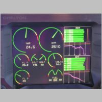
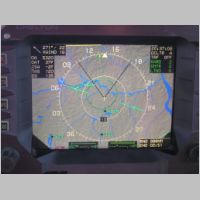
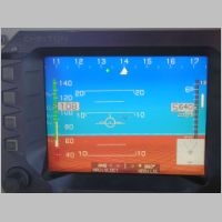
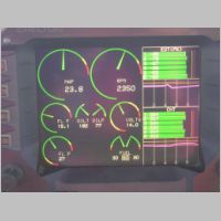
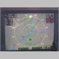
ROP Cruise
For the
first part of cruise,
I operated the engine RICH of peak (ROP). You can see the
temps
from peak on the EGT graphs above, using the peak finder
function.....I'm running between 55 and 96 degrees Rich of Peak.
I'm pushing 173 kts TAS (add 2 for my correction for
instrument
error), so about 175 kts on 15.1 gph. My cylinders are
fairly
close, with the middle 2 being the coldest at 332/334, and the outer 4
being all grouped very well together between 350 and 357. So
this
is FANTASTIC.
Climb Phase
This set of photos was taken during a normal climb to 6500'. You'll see I'm climing at approx. 110kts, and pushing about 20gph of fuel. Looking at my CHT's after the climb you'll see that whereas BEFORE the cylinder and cowl work I could easily see 410 degrees on climb, I'm now showing a max of 380. This is just fantastic for temps. Yeah, the OAT wasn't so warm, being 37F during the climb at one of the points, but I was seeing 410 during climb last winter when it was 10F on the GROUND. So this is a significant change! I know that I could possibly improve the cooling with louvers, but if 380 is all I see in climb, then what's going to happen on the cool end during cruise...could I be too cool in cruise?|
|
|
|
|
|
|
|
|
ROP Cruise
For the first part of cruise, I operated the engine RICH of peak (ROP). You can see the temps from peak on the EGT graphs above, using the peak finder function.....I'm running between 55 and 96 degrees Rich of Peak. I'm pushing 173 kts TAS (add 2 for my correction for instrument error), so about 175 kts on 15.1 gph. My cylinders are fairly close, with the middle 2 being the coldest at 332/334, and the outer 4 being all grouped very well together between 350 and 357. So this is FANTASTIC.
|
|
|
|
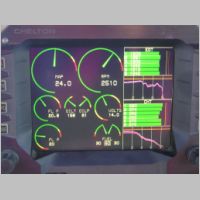
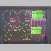
LOP Cruise
Now it's
time to cruise the
way I like to cruise. Lean it out and go 25-50 LOP or so
(yeah,
I need to improve the spread a bit, as I'm at 24 and 75 for the outer
edges of EGT temps, but it runs well), and now you can see I'm pulling
only 11.0gph, but I'm still getting 164kts...correct this by adding
2kts...for a speed of 166kts. Now look at the CHT's, and I
didn't
stay LOP too long...319 on the low end, and 345 on the high end.
If I were to leave it LOP for a while, you'd see those CHT's
drop
even further. I've been cautioned that I don't want to get
this
cooling too low, because you want the cylinders to get to a good
operating temp. I've been told anything from 310 to 340 for
ideal
lowest-end temps. I'm thinking if I were to add the Louvers,
I'd
probably need to cover them in the colder months, or I'd get too much
cooling. So for the time being, I'm not doing anything more,
and
I'll probably sell that set of louvers.
One other side note. Vic reported about 40 degrees F CHT drop
(during climb) after putting Microlon in his engine at an oil change.
I have some Microlon coming in a few days (will add it in a
few
weeks at the next change), so even if I saw 10-20F change in temps, I
would be very significantly low, and would not necessarily want to go
any further.
So that
wraps up my cooling
work for now on my engine. I'm getting into the cold season
here,
and I know I've already significantly lowered my temps. I'm
now
convinced that if you're seeing higher temps, you probably should look
VERY closely at your installation, because a very well done
installation, done per plans, should end up being very satisfactory for
cooling.
Site Home | N104CD Home
LOP Cruise
Now it's time to cruise the way I like to cruise. Lean it out and go 25-50 LOP or so (yeah, I need to improve the spread a bit, as I'm at 24 and 75 for the outer edges of EGT temps, but it runs well), and now you can see I'm pulling only 11.0gph, but I'm still getting 164kts...correct this by adding 2kts...for a speed of 166kts. Now look at the CHT's, and I didn't stay LOP too long...319 on the low end, and 345 on the high end. If I were to leave it LOP for a while, you'd see those CHT's drop even further. I've been cautioned that I don't want to get this cooling too low, because you want the cylinders to get to a good operating temp. I've been told anything from 310 to 340 for ideal lowest-end temps. I'm thinking if I were to add the Louvers, I'd probably need to cover them in the colder months, or I'd get too much cooling. So for the time being, I'm not doing anything more, and I'll probably sell that set of louvers.One other side note. Vic reported about 40 degrees F CHT drop (during climb) after putting Microlon in his engine at an oil change. I have some Microlon coming in a few days (will add it in a few weeks at the next change), so even if I saw 10-20F change in temps, I would be very significantly low, and would not necessarily want to go any further.
|
|
|
|
So that wraps up my cooling work for now on my engine. I'm getting into the cold season here, and I know I've already significantly lowered my temps. I'm now convinced that if you're seeing higher temps, you probably should look VERY closely at your installation, because a very well done installation, done per plans, should end up being very satisfactory for cooling.