RV-10 Building
GOTCHAS.....Read this before you start the project
Here we'll try to compile a list of things that you really should know
BEFORE you start on various sections. Contribute all you can, and
we'll help make those next generation of -10 builders have an even
easier time.
Vertical Stab
Horizontal Stab
Tailcone
Wings
Fuselage
Engine Installation
Elevator Trim Adjustment
Vertical
Stab
Vertical Stabilizer: DO
NOT try to force the nose ribs into the skin. Almost ALL builders
have found that they dented outward their VS skins by doing this.
You will need to grind maybe 1/8" or so off the nose of the nose
ribs (VS-1006, VS-1013, and VS-1005) before you put these ribs in.
Van's plans don't warn you
about this during the VS, but funny how they do add a warning later for
the HS.....well after you've already learned the lesson the hard way.
(see page 8-7 and check out Figure 2 where it shows how to avoid the
problem.) Thanks to Deems
Davis
#40406 for reminding me to post this!
Horizontal
Stab
Horizontal Stab: This
tip is basically a "Pay Attention" tip. Here is what he said
(edited a little for brevity):
"Well, it hit soon after finishing the rudder. The drawing on
page 8-5, Front Spar Assembly, is correct, but the mental gymnastics
leave a lot of room for error. The spar caps(HS-1013)
go trimmed side against the spar web, but that is only semi-obvious
from the drawing, because it is drawn with those parts away from you,
not facing you as they are when you clamp them in. The text is also
correct, but late in the day, reading only twice, instead of six times,
I screwed up." Thanks to Kelly McMullen for this!
Tailcone
Cutting Tailcone Longerson - See Below section in fuse
Tailcone Attach
Tailcone Attach (Drilling Longerons):
At
the
end of the fuselage longerons that stick into the tailcone just
below the curved roof area, there will be 4 holes that get drilled into
the tailcone longerons. Thanks to Bob Condrey for the tip, he
notes: The initial holes are match drilled using the F1046-B
template on page 29-3. They are then match drilled to the
tailcone sections and enlarged on page 32-3 step 4. Here's a photo from Bob, and the
specs:
Specific
measurements just in case there’s a scaling issue with the picture:
- Four bolt
hole centers are 7/16” from edge
- Aft bolt
hole center is 3/8” from aft end of longeron
- Hole
spacing is ¾” center to center
If
you received a QB fuselage, you probably don't have any holes in the
longerons, and you don't have the template either. In my case,
what I did was lay out a good 4 hole pattern, not knowing tha above
info. I don't see a problem with it, but now that we have the
info above, I'd use that. What I did was just leave a good end
edge distance on the rear one, and a little working space behind the
bulkhead on the front one, and then space the other 2 holes
evenly.
Elevator Trim Cable Attach Brackets
Whatever you do, you should probably not leave
your Elevator Trim attach brackets as-is. These are p/n WD-415.
There have already been cases of breakage both during construction, and
during flight. The original ones from the factory were not
consistently made with stainless material, and the welding is not
thorough enough to ensure safety. There are a few good ways to
deal with this.
Check this link for more.
Tailcone SB-8-6-1 and Trim Tab Rigging
I'll list this as a "gotcha" just because you DO NOT want to pass up
completing the tailcone SB 8-6-1
that Van's released. On one of the factory demonstrator RV-10's,
cracks were found in an aft bulkhead, and a doubler was sent out to be
installed on all RV-10's both flying and under construction.
Additonally, there is a gotcha relating to Trim Tab Rigging that I
explain HERE.
Wings
Don't Deburr That Hole!
When doing the rear spar on the wings, page 15-2 where you work with
the aileron brackets:
Don't
deburr the W-1013A bracket where the bearing goes, because it may
end
up oversized and the bearing needs to be a pressed fit!
Thanks Jim, 40384!
WATCH OUT when doing
those wing
root fairing nutplates!
When you're countersinking and installing the wing root fairing holes
on the inboard side of the wings, watch out that you put the PROPER
nutplate type in the location on the hole in this picture. A few
people now have used the same nutplates as the others, which won't
allow that nice countersunk hole to line up with the hole on the root
fairing. I myself did this. My fix was to fill that hole
with JB Weld, and re-drill and re-countersink the proper hole and use
the proper nutplate, so it matched the fairing hole. Not perfect,
but it works.

J-Channel Stiffners - From Mark C.
"Sounds like I’m not the only one to make this mistake. But in the wing
kit, section 13 where you drill the J-Channel stiffeners inside the
main spar. Step 7 and Figure 3 refer to nesting the shorter channel
inside the longer channel. This lead me and others to line up the two
J-Channels with the inboard portion of the main spar flange. But if you
look closely, you can see that the LONG J-Channel is flush with the
OUTBOARD portion of the spar flange, and the SHORT J-Channel is flush
with the inboard. Rather than “nesting” the term OVERLAP would be more
appropriate as the SHORT channel with OVERLAP the long channel where
they meet. It’s clear if you look at the picture and know what to
look for, but on first glance it’s deceiving.
Fuselage
Tough Rivets - Do Them Early -
Thanks Chris Johnston
I'm merrily riveting along towards the end of step 29, and as I'm
riveting F-1040 (upper fuse channel), I notice that there are nutplate
holes on the upper flange that have no nutplates. furthermore, after
you rivet it to the bulkhead, you won't be able to get at one of the
noles needed for one of the nutplates. I noticed many steps later that
there's an access cover that screws into these nonexistant nutplates.
I found a little reference to this in the archives and I'll be
drilling out a couple rivets to install these nutplates now. NOTE - IT
WOULD BE MUCH MORE DIFFICULT AFTER THE FORWARD FUSE SIDE SKIN IS
RIVETED ON. this is yet another shortcoming in the (now becoming
infamous around here) step 29.
113" Fuse
Longeron Angle
- Mark it "don't cut" - Thanks Jay Brinkmeyer
Several of the fuse longeron diagrams have two dimensions shown along
the same face within a single figure. That is, one diagram is used to
show two different pieces each with different dimensions. I doubt if my
engineering graphics professor would have given this scheme a passing
mark.
Measure twice, think longer and cut once? Nah.
I cut the smaller pieces first without looking around the shop long
enough. If you do like me you might wind up needing a 113" longeron
that is now in two pieces (dooh!). Shipping a $15 part with dimensions
over 8' from Oregon is several hundred dollars as it has to go by
freight.
Luckily I found a local source that supplies the equivalent part. If
there's anyone in the Colorado area in the same boat let me know as I
now have extra AA6-125 3/4 x 3/4.
This is the plans page being referred
to:
Section 10 Page 5
http://www.myrv10.com/Plans/RV10_Plans_sec10-pg05.html
----- More from Brian Douglas ------
Yeah, I'm in a similar boat with a tailcone J-Channel. Like a
doofus (sp?) I cut one of the 93"ers too short and had to order a new
one from Vans. <snip> Anyway, let that be a lesson to the
guys/girls just starting. Cut the long pieces first!! (Tim - Cut the
long ones, mark them, and set them aside)
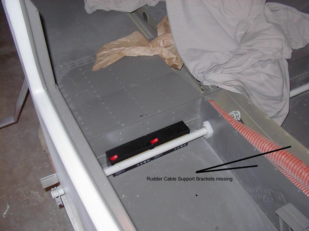
Don't
forget
the
Rudder Cable Support Bracket - Thanks Ron
McGann
1.
Page
38-9.
Don't forget to install the F-1016H cable support
brackets (see here).
2.
Page
38-6.
Install the brass fittings to one end of each of the
43" brake lines AFTER routing through the bushings in the F-1039D
bracket. BTW, I found the best way to insert the brass inserts
into the plastic brake line. Put a nail of slightly smaller
diameter to the pin into a block of wood. Place the insert
over the nail, insert the tube in some boiling water for a few
minutes, then press the tube down over the pin and nail. The nail
will pass harmlessy into the tube, and voila - one completed assembly.
3.
When
bending
the forward brake lines, be aware that they will pass
through a slot in the forward tunnel cover. If you bend the lines
too far below the F-100K recess, you will need to trim the tunnel cover
(ask how I know).
4.
attach
the
F-1089 Elevator pushrod to the F-1063 Elevator Idler Arm
assembly BEFORE installing the idler arm assembly to the brackets (MUCH
easier to get those AN960-10L in!). Don't re-install the
battery/bellcrank mount per page 39-5 until the pushrods are installed.
Engine Installation
Filtered Air Box - See THIS Link for
info regarding a doubler that you will want to install in your filtered
air box that is not in the plans.
Elevator
Trim
Adjustment
If you haven't found this section yet, make sure you read up on
elevator (and aileron trimming) adjustments. There are some
issues you should be aware of.
